Part number:
CM1200HC-34H
Manufacturer:
Mitsubishi Electric
File Size:
93.74 KB
Description:
Igbt.
CM1200HC-34H Datasheet (93.74 KB)
Datasheet Details
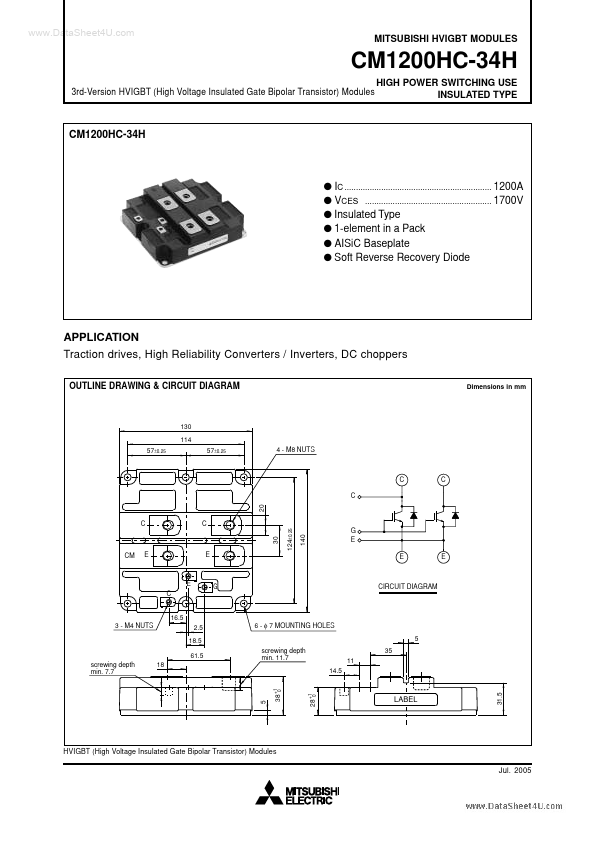
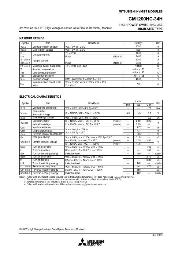
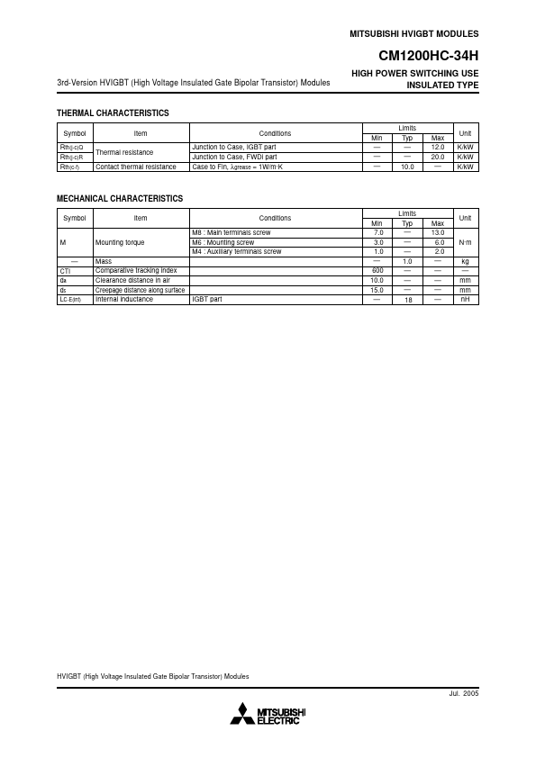
CM1200HC-34H
Mitsubishi Electric
93.74 KB
Igbt.
📁 Related Datasheet
CM1200HC-50H IGBT Module (Powerex Power Semiconductors)
CM1200HC-50H IGBT (Mitsubishi Electric)
CM1200HC-66H IGBT (Mitsubishi Electric)
CM1200HC-90R HVIGBT Modules (Mitsubishi)
CM1200HCB-34N HVIGBT Modules (Mitsubishi)
CM1200HA-24J IGBT Module (Powerex Power Semiconductors)
CM1200HA-34H IGBT Module (Powerex Power Semiconductors)
CM1200HA-34H IGBT (Mitsubishi Electric)
CM1200HC-34H Distributor