Datasheet4U Logo Datasheet4U.com

IXTT140N10P - Power MOSFET

This page provides the datasheet information for the IXTT140N10P, a member of the IXTQ140N10P Power MOSFET family.

Datasheet Summary

Features

  • l l 1.13/10 Nm/lb. in. 5.5 5.0 g g l International standard packages Unclamped Inductive Switching (UIS) rated Low package inductance - easy to drive and to protect Symbol Test Conditions (TJ = 25° C, unless otherwise specified) BVDSS VGS(th) IGSS IDSS RDS(on) VGS = 0 V, ID = 250 µA VDS = VGS, ID = 250µA VGS = ±20 VDC, VDS = 0 VDS = VDSS VGS = 0 V TJ = 175° C Characteristic Values Min. Typ. Max. 100 3.0 5.0 ±100 25 500 11 9 V V nA µA µA mΩ mΩ Advantages l l l Easy to mount Space savings Hi.

📥 Download Datasheet

Datasheet preview – IXTT140N10P

Datasheet Details

Part number IXTT140N10P
Manufacturer IXYS Corporation
File Size 202.82 KB
Description Power MOSFET
Datasheet download datasheet IXTT140N10P Datasheet
Additional preview pages of the IXTT140N10P datasheet.
Other Datasheets by IXYS Corporation

Full PDF Text Transcription

Click to expand full text
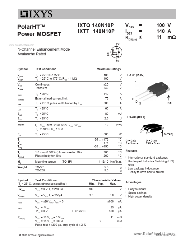
PolarHTTM Power MOSFET www.datasheet4u.com IXTQ 140N10P IXTT 140N10P VDSS ID25 RDS(on) = = ≤ 100 V 140 A 11 mΩ N-Channel Enhancement Mode Avalanche Rated Symbol VDSS VDGR VGS VGSM ID25 ID(RMS) IDM IAR EAR EAS dv/dt PD TJ TJM Tstg TL TSOLD Md Weight Test Conditions TJ = 25° C to 175° C TJ = 25° C to 175° C; RGS = 1 MΩ Continuous Transient TC = 25° C External lead current limit TC = 25° C, pulse width limited by TJM TC = 25° C TC = 25° C TC = 25° C IS ≤ IDM, di/dt ≤ 100 A/µs, VDD ≤ VDSS, TJ ≤150° C, RG = 4 Ω TC = 25° C Maximum Ratings 100 100 ±20 ±30 140 75 300 60 80 2.5 10 600 -55 ... +175 175 -55 ... +150 V V V V A A A A mJ J V/ns W °C °C °C °C °C G = Gate S = Source G S D = Drain TAB = Drain D (TAB) TO-3P (IXTQ) G D S (TAB) TO-268 (IXTT) 1.6 mm (0.062 in.
Published: |