Datasheet4U Logo Datasheet4U.com

IXTQ180N10T - Power MOSFET

Download the IXTQ180N10T datasheet PDF. This datasheet also covers the IXTH180N10T variant, as both devices belong to the same power mosfet family and are provided as variant models within a single manufacturer datasheet.

Features

  • Ultra-low On Resistance Unclamped Inductive Switching (UIS) rated Low package inductance - easy to drive and to protect 175 ° C Operating Temperature Advantages Easy to mount Space savings High power density Symbol Test Conditions (TJ = 25° C unless otherwise specified) BVDSS VGS = 0 V, ID = 250 µA VGS(th) VDS = VGS, ID = 250 µA IGSS VGS = ± 20 V, VDS = 0 V IDSS VDS = VDSS VGS = 0 V TJ = 150° C RDS(on) VGS = 10 V, ID = 25 A, Notes 1, 2 Characteristic Values Min. Typ. Max. 100 V 2.

📥 Download Datasheet

Note: The manufacturer provides a single datasheet file (IXTH180N10T-IXYSCorporation.pdf) that lists specifications for multiple related part numbers.

Full PDF Text Transcription

Click to expand full text
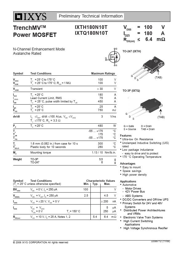
Preliminary Technical Information TrenchMVTM Power MOSFET IXTH180N10T IXTQ180N10T N-Channel Enhancement Mode Avalanche Rated VDSS = ID25 = RDS(on) ≤ 100 180 6.4 V A mΩ TO-247 (IXTH) Symbol VDSS VDGR VGSM ID25 ILRMS IDM IAR EAS dv/dt PD TJ TJM Tstg TL TSOLD Md Weight Test Conditions TJ = 25° C to 175° C TJ = 25° C to 175° C; RGS = 1 MΩ Transient TC = 25° C Lead Current Limit, RMS TC = 25° C, pulse width limited by TJM TC = 25° C TC = 25° C IS ≤IDM, di/dt ≤100 A/µs, VDD ≤VDSS TJ ≤175° C, RG = 3.3 Ω TC = 25° C 1.6 mm (0.062 in.) from case for 10 s Plastic body for 10 seconds Mounting torque TO-3P TO-247 Maximum Ratings 100 100 ± 30 180 75 450 25 750 V V V A A A A mJ 3 V/ns G DS TO-3P (IXTQ) G D S (TAB) (TAB) 480 W -55 ... +175 175 -55 ... +175 °C °C °C 300 °C 260 °C 1.
Published: |