Datasheet4U Logo Datasheet4U.com

HGTG40N60B3 - N-Channel IGBT

Description

Symbol Ratings Units Collector to Emitter Voltage BVCES 600 V Collector Current Continuous At TC = 25°C At TC = 110°C IC25 70 A IC110 40 Collector Current Pulsed (Note 1) Gate to Emitter Voltage Continuous ICM 330 A VGES ±20 V Gate to Emitter Voltage Pulsed VGEM ±30 V Switch

Features

  • of MOSFETs and bipolar transistors. The device has the high input impedance of a MOSFET and the low on.
  • state conduction loss of a bipolar transistor. The much lower on.
  • state voltage drop varies only moderately between 25°C and 150°C. The IGBT is ideal for many high voltage switching.

📥 Download Datasheet

Datasheet preview – HGTG40N60B3

Datasheet Details

Part number HGTG40N60B3
Manufacturer ON Semiconductor
File Size 398.27 KB
Description N-Channel IGBT
Datasheet download datasheet HGTG40N60B3 Datasheet
Additional preview pages of the HGTG40N60B3 datasheet.
Other Datasheets by ON Semiconductor

Full PDF Text Transcription

Click to expand full text
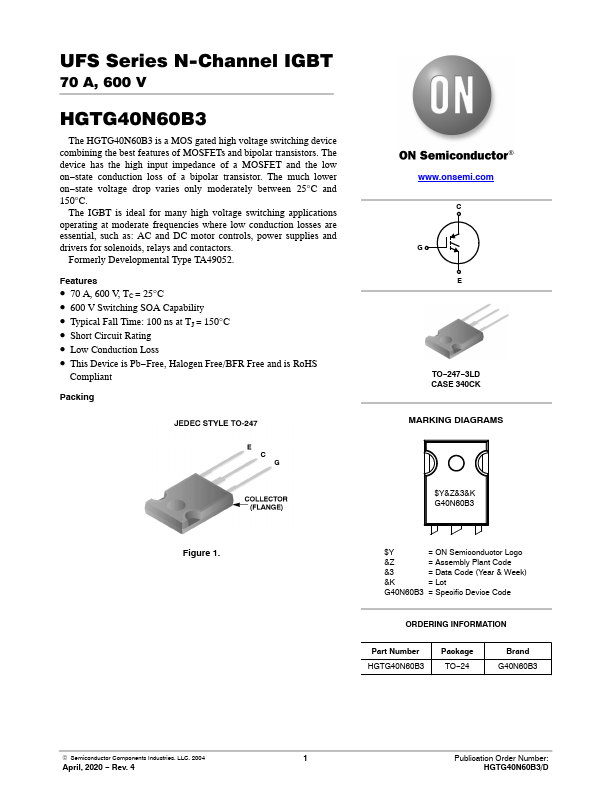
UFS Series N-Channel IGBT 70 A, 600 V HGTG40N60B3 The HGTG40N60B3 is a MOS gated high voltage switching device combining the best features of MOSFETs and bipolar transistors. The device has the high input impedance of a MOSFET and the low on−state conduction loss of a bipolar transistor. The much lower on−state voltage drop varies only moderately between 25°C and 150°C. The IGBT is ideal for many high voltage switching applications operating at moderate frequencies where low conduction losses are essential, such as: AC and DC motor controls, power supplies and drivers for solenoids, relays and contactors. Formerly Developmental Type TA49052.
Published: |