Datasheet4U Logo Datasheet4U.com

IXTX600N04T2 - Power MOSFET

Download the IXTX600N04T2 datasheet PDF. This datasheet also covers the IXTK600N04T2 variant, as both devices belong to the same power mosfet family and are provided as variant models within a single manufacturer datasheet.

Features

  • z z z z z International Standard Packages High Current Handling Capability Fast Intrinsic Diode Avalanche Rated Low R DS(on) Advantages z z Symbol Test Conditions (TJ = 25°C Unless Otherwise Specified) BVDSS VGS(th) IGSS IDSS RDS(on) VGS = 0V, ID = 250µA VDS = VGS, ID = 250µA VGS = ± 20V, VDS = 0V VDS = VDSS, VGS= 0V TJ = 150°C Characteristic Values Min. Typ. Max. 40 1.5 3.5 ± 200 V V nA z Easy to Mount Space Savings High Power Density.

📥 Download Datasheet

Note: The manufacturer provides a single datasheet file (IXTK600N04T2-IXYS.pdf) that lists specifications for multiple related part numbers.

Full PDF Text Transcription

Click to expand full text
Advance Technical Information 
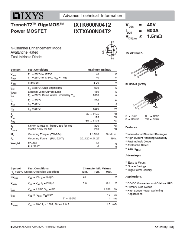
TrenchT2TM GigaMOS TM Power MOSFET 
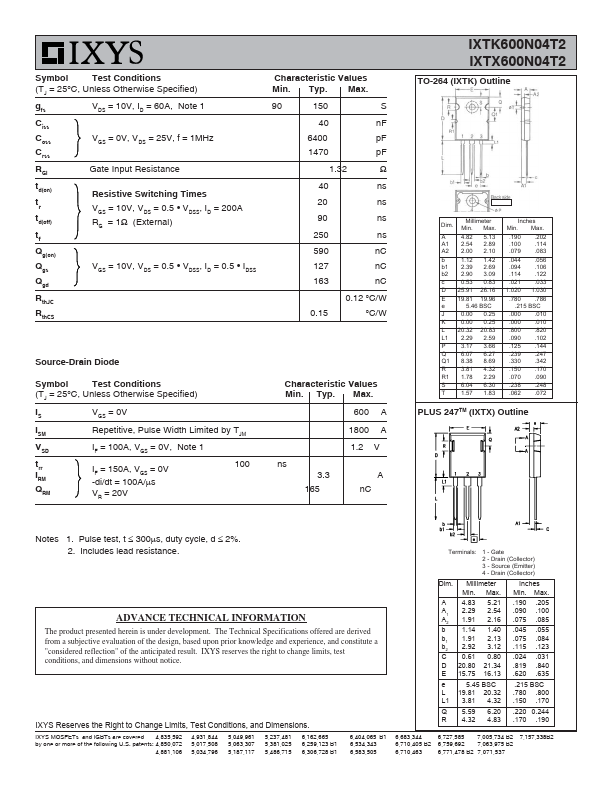
IXTK600N04T2 IXTX600N04T2 VDSS ID25 = = RDS(on) ≤ 40V 600A 1.5mΩ N-Channel Enhancement Mode Avalanche Rated Fast Intrinsic Diode TO-264 (IXTK) Symbol VDSS VDGR VGSM ID25 IL(RMS) IDM IA EAS PD TJ TJM Tstg TL TSOLD Md FC Weight Test Conditions TJ = 25°C to 175°C TJ = 25°C to 175°C, RGS = 1MΩ Transient TC = 25°C (Chip Capability) External Lead Current Limit TC = 25°C, Pulse Width Limited by TJM TC = 25°C TC = 25°C TC = 25°C Maximum Ratings 40 40 ± 20 600 160 1600 200 3 1250 -55 ... +175 175 -55 ... +175 V V V A A A A J W °C °C °C °C °C Nm/lb.in. N/lb. g g G D S Tab PLUS247 (IXTX) G D S Tab G = Gate S = Source D = Drain Tab = Drain 1.6mm (0.062 in.
Published: |