Datasheet4U Logo Datasheet4U.com

IXGT25N250 - High Voltage IGBT

Download the IXGT25N250 datasheet PDF. This datasheet also covers the IXGH25N250 variant, as both devices belong to the same high voltage igbt family and are provided as variant models within a single manufacturer datasheet.

Features

  • Test Conditions IC = 250 μA, VGE = 0 V IC = 250 μA, VCE = VGE V = 0.8.
  • V CE CES VGE = 0 V VCE = 0 V, VGE = ±20 V IC = 25 A, VGE = 15 V IC = 75 A TO-247 TO-268 6 g 4 g Characteristic Values (TJ = 25°C unless otherwise specified) Min. Typ. Max. 2500 V 3.0 5.0 V TJ = 125°C 50 μA 1 mA ±100 nA 2.9 V 5.2 V High peak current capability Low saturation voltage MOS Gate turn-on -drive simplicity Rugged NPT structure Molding epoxies meet UL 94 V-0 flammability classification.

📥 Download Datasheet

Note: The manufacturer provides a single datasheet file (IXGH25N250-IXYS.pdf) that lists specifications for multiple related part numbers.

Full PDF Text Transcription

Click to expand full text
Preliminary Technical Information
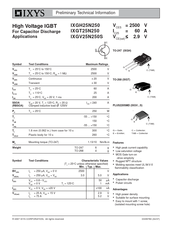
 High Voltage IGBT For Capacitor Discharge Applications 
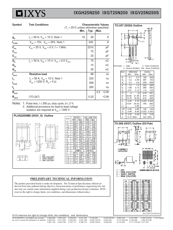
IXGH25N250 IXGT25N250 IXGV25N250S VCES = 2500 V IC25 = 60 A V CE(sat) ≤ 2.9 V TO-247 (IXGH) Symbol V CES VCGR VGES VGEM IC25 IC110 ICM SSOA (RBSOA) PC TJ TJM Tstg T L TSOLD Md Weight Symbol BVCES VGE(th) I CES IGES VCE(sat) Test Conditions T = 25°C to 150°C J TJ = 25°C to 150°C; RGE = 1 MΩ Continuous Transient TC = 25°C TC = 110°C TC = 25°C, VGE = 20 V, 1 ms VGE= 20 V, TJ = 125°C, RG = 20 Ω Clamped inductive load @ 1250V TC = 25°C 1.6 mm (0.062 in.) from case for 10 s Plastic body for 10 s Maximum Ratings 2500 V 2500 V G CE C (TAB) ± 20 V TO-268 (IXGT) ± 30 V 60 A 25 A 200 A G E C (TAB) ICM = 240 A PLUS220SMD (IXGV...S) 250 W -55 ... +150 150 -55 ...
Published: |