Datasheet4U Logo Datasheet4U.com

IXFK26N60Q - HiPerFET Power MOSFET

Download the IXFK26N60Q datasheet PDF. This datasheet also covers the IXFX26N60Q variant, as both devices belong to the same hiperfet power mosfet family and are provided as variant models within a single manufacturer datasheet.

Features

  • l l Symbol Test Conditions Characteristic Values (TJ = 25°C, unless otherwise specified) min. typ. max. 600 2.5 TJ = 25°C TJ = 125°C 4.5 ± 200 25 1 0.25 V V nA µA mA Ω l l l l l VDSS VGS(th) IGSS IDSS RDS(on) VGS = 0 V, ID = 250µA VDS = VGS, ID = 4 mA VGS = ±20 VDC, VDS = 0 VDS = VDSS VGS = 0 V Low gate charge International standard packages Epoxy meet UL 94 V-0, flammability classification Low RDS (on).

📥 Download Datasheet

Note: The manufacturer provides a single datasheet file (IXFX26N60Q_IXYS.pdf) that lists specifications for multiple related part numbers.

Full PDF Text Transcription

Click to expand full text
Advance Technical Information www.DataSheet4U.com 
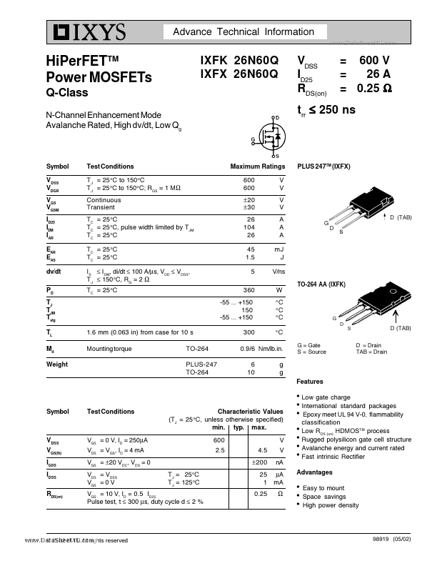
HiPerFETTM Power MOSFETs Q-Class N-Channel Enhancement Mode Avalanche Rated, High dv/dt, Low Qg IXFK 26N60Q IXFX 26N60Q VDSS ID25 RDS(on) = 600 V = 26 A = 0.25 Ω trr ≤ 250 ns Symbol VDSS VDGR VGS VGSM ID25 IDM IAR EAR EAS dv/dt PD TJ TJM Tstg TL Md Weight Test Conditions TJ = 25°C to 150°C TJ = 25°C to 150°C; RGS = 1 MΩ Continuous Transient TC = 25°C TC = 25°C, pulse width limited by TJM TC = 25°C TC = 25°C TC = 25°C IS ≤ IDM, di/dt ≤ 100 A/µs, VDD ≤ VDSS, TJ ≤ 150°C, RG = 2 Ω TC = 25°C Maximum Ratings 600 600 ± 20 ± 30 26 104 26 45 1.5 5 360 -55 ... +150 150 -55 ... +150 V V V V A A A mJ J V/ns W °C °C °C °C
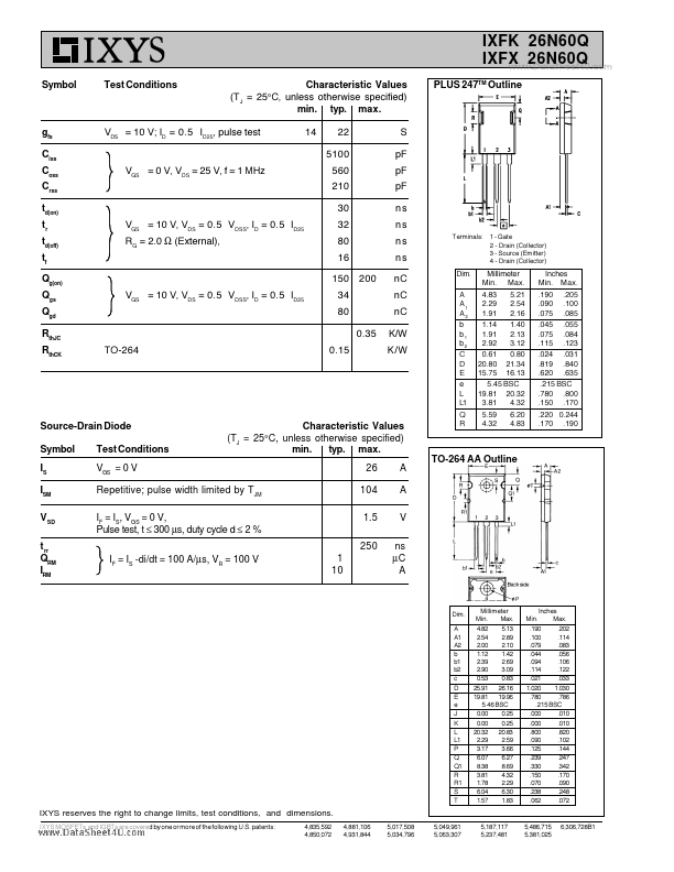
 PLUS 247TM (IXFX) D (TAB) G D TO-264 AA (IXFK) G D S 1.6 mm (0.
Published: |