Datasheet4U Logo Datasheet4U.com

IXFK200N10P - Polar HiPerFET Power MOSFET

Download the IXFK200N10P datasheet PDF. This datasheet also covers the IXFX200N10P variant, as both devices belong to the same polar hiperfet power mosfet family and are provided as variant models within a single manufacturer datasheet.

Features

  • z z C = Collector Tab = Collector z International standard packages Unclamped Inductive Switching (UIS) rated Low package inductance - easy to drive and to protect Advantages z z z RDS(on) VGS = 10 V, ID = 0.5 ID25 VGS = 15 V, ID = 400A Pulse test, t ≤ 300 µs, duty cycle d ≤ 2 % Easy to mount Space savings High power density DS99239B(03/05) © 2005 IXYS All rights reserved IXFK 200N10P Symbol Test Conditions Characteristic Values (TJ = 25°C, unless otherwise specified) Min. Typ. Max. 60.

📥 Download Datasheet

Note: The manufacturer provides a single datasheet file (IXFX200N10P_IXYS.pdf) that lists specifications for multiple related part numbers.

Full PDF Text Transcription

Click to expand full text
Advanced Technical Information www.DataSheet4U.com PolarTM HiPerFET Power MOSFET N-Channel Enhancement Mode 
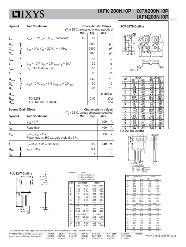
IXFN 200N10P IXFK 200N10P IXFX 200N10P VDSS ID25 RDS(on) = 100 V = 200 A = 7.5 mΩ Symbol VDSS VDGR VGS VGSM ID25 ID(RMS) IDM IAR EAR EAS dv/dt PD TJ TJM Tstg VISOL Md Weight Test Conditions TJ = 25°C to 175°C TJ = 25°C to 175°C; RGS = 1 MΩ Maximum Ratings 100 100 ± 20 ± 30 V V V V A A A A mJ J V/ns W °C °C °C V~ miniBLOC, SOT-227 B (IXFN) E153432 S G S D G = Gate S = Source D = Drain TC = 25°C External lead current limit TC = 25°C, pulse width limited by TJM TC = 25°C TC = 25°C TC = 25°C IS ≤ IDM, di/dt ≤ 100 A/µs, VDD ≤ VDSS, TJ ≤ 150°C, RG = 4 Ω TC = 25°C 200 100 400 60 100 4 10 800 -55 ... +175 175 -55 ...
Published: |