Datasheet4U Logo Datasheet4U.com

IXGT15N120B2D1 - IGBT

Download the IXGT15N120B2D1 datasheet PDF. This datasheet also covers the IXGH15N120B2D1 variant, as both devices belong to the same igbt family and are provided as variant models within a single manufacturer datasheet.

Features

  • z International standard packages: JEDEC TO-247AD & TO-268 z IGBT and anti-parallel FRED in one package z MOS Gate turn-on - drive simplicity z Fast Recovery Expitaxial Diode (FRED) - soft recovery with low IRM Symbol Test Conditions (TJ = 25°C, unless otherwise specified) BV CES VGE(th) I C = 250 μA, V GE = 0 V IC = 250 μA, VCE = VGE ICES VCE = VCES V =0V GE I GES V CE = 0 V, V GE = ±20 V VCE(sat) IC = ICE90, VGE = 15 Characteristic Values Min. Typ. Max. 1200 2.5 V.

📥 Download Datasheet

Note: The manufacturer provides a single datasheet file (IXGH15N120B2D1-IXYS.pdf) that lists specifications for multiple related part numbers.

Full PDF Text Transcription

Click to expand full text
Advance Technical Information 
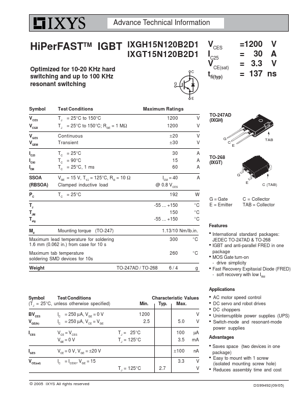
HiPerFASTTM IGBT IXGH15N120B2D1 IXGT15N120B2D1 Optimized for 10-20 KHz hard switching and up to 100 KHz resonant switching VCES IC25 VCE(sat) tfi(typ) =1200 V = 30 A = 3.3 V = 137 ns Symbol Test Conditions Maximum Ratings VCES VCGR VGES VGEM IC25 IC90 I CM SSOA (RBSOA) PC TJ TJM Tstg TJ = 25°C to 150°C TJ = 25°C to 150°C; RGE = 1 MΩ Continuous Transient TC = 25°C TC = 90°C T C = 25°C, 1 ms V GE = 15 V, T VJ = 125°C, R G = 10 Ω Clamped inductive load TC = 25°C 1200 V 1200 V ±20 V ±30 V 30 A 15 A 60 A I = 40 A CM @ 0.8 V CES 192 W -55 ... +150 °C 150 °C -55 ... +150 °C Md Mounting torque (TO-247) Maximum lead temperature for soldering 1.6 mm (0.062 in.
Published: |