Datasheet4U Logo Datasheet4U.com

IXGQ85N33PCD1 - High Speed IGBT

Features

  • International standard package.
  • Fast tfi for minimum turn off switching losses.
  • MOS Gate turn-on - drive simplicity.
  • Positive dVsat/dt for paralleling 260 1.3/10 5.5 Nm/lb. in. g ≤ Symbol Test Conditions (TJ = 25°C unless otherwise specified) Characteristic Values Min. Typ. Max. V GE(th) IC = 1 mA, VCE = VGE 3.0 6.0 V ICES VCE = 330 V VGE = 0 V TJ = 125°C 1 μA 200 μA IGES VCE = 0 V, VGE = ±20 V ±100 nA VCE(sat) VGE = 15V, Note 1 IC = 50 A TJ =.

📥 Download Datasheet

Datasheet preview – IXGQ85N33PCD1

Datasheet Details

Part number IXGQ85N33PCD1
Manufacturer IXYS
File Size 139.11 KB
Description High Speed IGBT
Datasheet download datasheet IXGQ85N33PCD1 Datasheet
Additional preview pages of the IXGQ85N33PCD1 datasheet.
Other Datasheets by IXYS

Full PDF Text Transcription

Click to expand full text
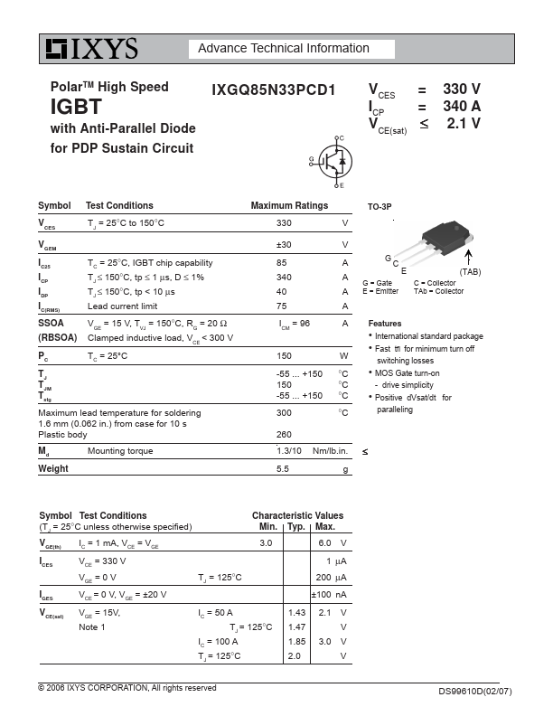
Advance Technical Information PolarTM High Speed IGBT with Anti-Parallel Diode for PDP Sustain Circuit IXGQ85N33PCD1 VCES ICP VCE(sat) = = ≤ 330 V 340 A 2.1 V Symbol V CES Test Conditions TJ = 25°C to 150°C VGEM IC25 ICP IDP IC(RMS) SSOA (RBSOA) TC = 25°C, IGBT chip capability TJ ≤ 150°C, tp ≤ 1 μs, D ≤ 1% TJ ≤ 150°C, tp < 10 μs Lead current limit VGE = 15 V, TVJ = 150°C, RG = 20 Ω Clamped inductive load, VCE < 300 V PC TC = 25°C TJ TJM T stg Maximum lead temperature for soldering 1.6 mm (0.062 in.) from case for 10 s Plastic body Md Mounting torque Weight Maximum Ratings 330 V TO-3P ±30 V 85 340 40 A GC A E (TAB) G = Gate C = Collector A E = Emitter TAb = Collector 75 A ICM = 96 A 150 -55 ... +150 150 -55 ...
Published: |