Description
x8
A0-A12
Row Address Input
A0-A9, A11
Column Address Input
BA0, BA1
Bank Select Address
DQ0
DQ7
Data I/O
CK, CK
System Clock Input
CKE
Clock Enable
CS Chip Select
CAS
Column Address Strobe Command
RAS
Row Address Strobe Command
WE Write Enable
4
66 VSS 65 DQ7 64 VSSQ 63 NC 62 DQ6 61 VDDQ 60 NC 59 DQ5 58 VSSQ 57 NC 56 DQ4 55 VDDQ 54 NC 53 NC 52 VSSQ 51 DQS 50 NC 49 VREF 48 VSS 47 DM 46 CK 45 CK 44 CKE 43 NC 42 A12 41 A11 40 A9 39 A8 38 A7 37 A6 36 A5 35 A4 34 VSS
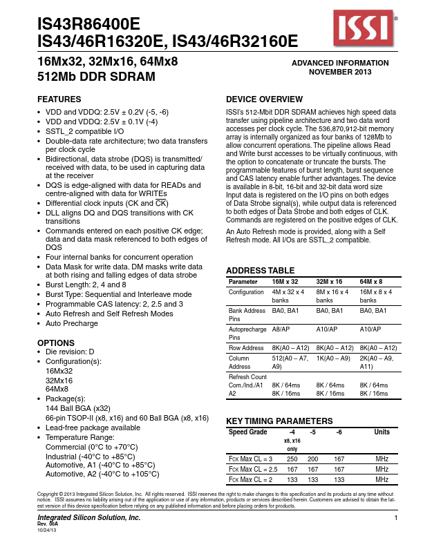
Features
- VDD and VDDQ: 2.5V ± 0.2V (-5, -6).
- VDD and VDDQ: 2.5V ± 0.1V (-4).
- SSTL_2 compatible I/O.
- Double-data rate architecture; two data transfers
per clock cycle.
- Bidirectional, data strobe (DQS) is transmitted/
received with data, to be used in capturing data at the receiver.
- DQS is edge-aligned with data for READs and centre-aligned with data for WRITEs.
- Differential clock inputs (CK and CK).
- DLL aligns DQ and DQS tran.
 IS43R86400E-IntegratedSiliconSolution.pdf