Datasheet Details
| Part number | BLS9G2934LS-400 |
|---|---|
| Manufacturer | Ampleon |
| File Size | 613.13 KB |
| Description | LDMOS S-band radar power transistor |
| Datasheet |
 BLS9G2934LS-400 Datasheet BLS9G2934LS-400 Datasheet
|
|
|
Download the BLS9G2934LS-400 datasheet PDF. This datasheet also covers the BLS9G2934L-400 variant, as both devices belong to the same ldmos s-band radar power transistor family and are provided as variant models within a single manufacturer datasheet.
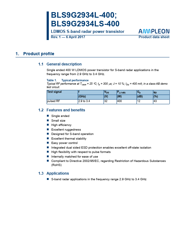
Single ended 400 W LDMOS power transistor for S-band radar applications in the frequency range from 2.9 GHz to 3.4 GHz.
Table 1.
Typical performance Typical RF performance at Tcase = 25 C; tp = 300 s; = 10 %; IDq = 400 mA; in a class-AB demo test circuit.
| Part number | BLS9G2934LS-400 |
|---|---|
| Manufacturer | Ampleon |
| File Size | 613.13 KB |
| Description | LDMOS S-band radar power transistor |
| Datasheet |
BLS9G2934LS-400 Datasheet
|
|
|
|
| Part Number | Description | Manufacturer |
|---|---|---|
| BLS2731-10 | Microwave power transistor | NXP |
| BLS2731-110 | Microwave power transistor | NXP |
| BLS2731-20 | Microwave power transistor | NXP |
| BLS2731-50 | Microwave power transistor | NXP |
| BLS2933-100 | Microwave power LDMOS transistor | NXP |
| Part Number | Description |
|---|---|
| BLS9G2934L-400 | LDMOS S-band radar power transistor |
| BLS9G2729L-350 | LDMOS S-band radar power transistor |
| BLS9G2729LS-350 | LDMOS S-band radar power transistor |
| BLS9G2731L-400 | LDMOS S-band radar power transistor |
| BLS9G2731LS-400 | LDMOS S-band radar power transistor |
The following content is an automatically extracted verbatim text from the original manufacturer datasheet and is provided for reference purposes only.