IRF8113GPbF Description
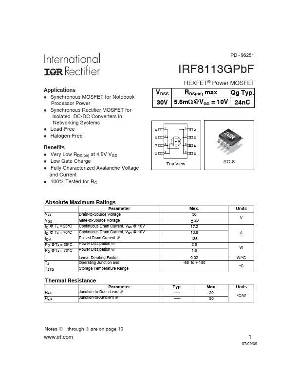
Applications l Synchronous MOSFET for Notebook Processor Power l Synchronous Rectifier MOSFET for Isolated DC-DC Converters in Networking Systems l Lead-Free l Halogen-Free Benefits l Very Low RDS(on) at 4.5V VGS l Low Gate Charge l Fully Characterized Avalanche Voltage and Current l 100% Tested for RG PD - 96251 IRF8113GPbF VDSS 30V HEXFET® Power MOSFET RDS(on) max Qg Typ. 20 50 Units V A W W/°C °C Units °C/W Notes...
IRF8113GPbF Key Features
- Synchronous MOSFET for Notebook Processor Power
- Synchronous Rectifier MOSFET for Isolated DC-DC Converters in Networking Systems
- Lead-Free
- Halogen-Free Benefits
- Very Low RDS(on) at 4.5V VGS
- Low Gate Charge
- Fully Characterized Avalanche Voltage and Current
- 100% Tested for RG PD - 96251 IRF8113GPbF VDSS 30V HEXFET® Power MOSFET RDS(on) max Qg Typ. :5.6m @VGS =