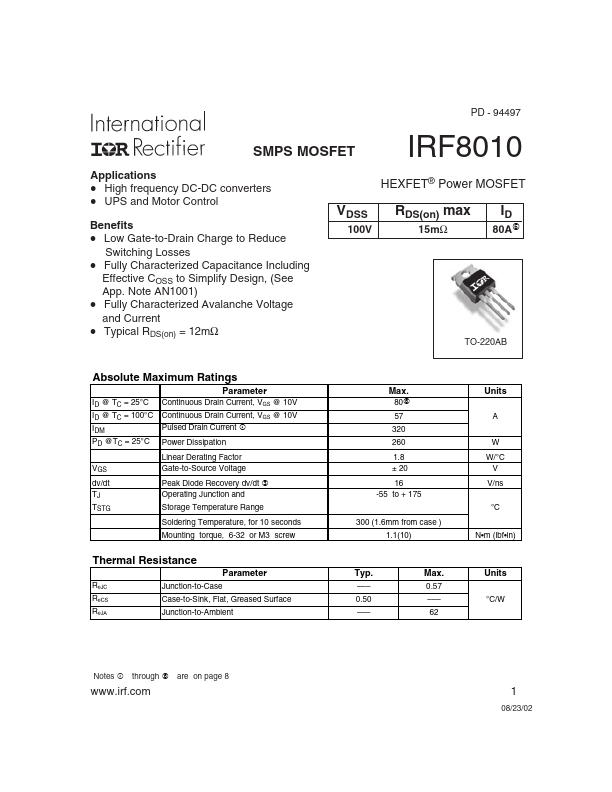
IRF8010
- 94497
SMPS MOSFET
Applications High frequency DC-DC converters UPS and Motor Control Benefits Low Gate-to-Drain Charge to Reduce Switching Losses Fully Characterized Capacitance Including Effective COSS to Simplify Design, (See App. Note AN1001) Fully Characterized Avalanche Voltage and Current Typical RDS(on) = 12mΩ
HEXFET® Power MOSFET
VDSS
100V
RDS(on) max
15mΩ
80A
TO-220AB
Absolute Maximum Ratings
Parameter
ID @ TC = 25°C ID @ TC = 100°C IDM PD @TC = 25°C VGS dv/dt TJ TSTG Continuous Drain Current, VGS @ 10V Continuous Drain Current, VGS @ 10V Pulsed Drain Current Power Dissipation Linear Derating Factor Gate-to-Source Voltage Peak Diode Recovery dv/dt Operating Junction and Storage Temperature Range Soldering Temperature, for 10 seconds Mounting torque, 6-32 or M3 screw 300 (1.6mm from case ) 1.1(10) N- m (lbf- in)
Max.
80 57 320 260 1.8 ± 20 16 -55 to + 175
Units
A W W/°C V V/ns °C
Thermal Resistance
Parameter
RθJC RθCS RθJA Junction-to-Case Case-to-Sink,...