Datasheet Details
| Part number | IXFT120N15P |
|---|---|
| Manufacturer | IXYS (Littelfuse) |
| File Size | 612.50 KB |
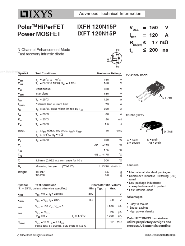
| Description | Polar MOSFETs |
| Datasheet |
 IXFT120N15P Datasheet IXFT120N15P Datasheet
|
|
|
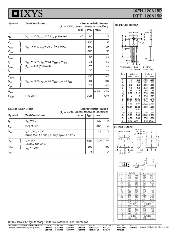
Download the IXFT120N15P datasheet PDF. This datasheet also covers the IXFH120N15P variant, as both devices belong to the same polar mosfets family and are provided as variant models within a single manufacturer datasheet.
| Part number | IXFT120N15P |
|---|---|
| Manufacturer | IXYS (Littelfuse) |
| File Size | 612.50 KB |
| Description | Polar MOSFETs |
| Datasheet |
IXFT120N15P Datasheet
|
|
|
|
| Part Number | Description | Manufacturer |
|---|---|---|
| IXFT12N100 | Power MOSFETs | IXYS |
| IXFT100N30X3HV | N-Channel Power MOSFET | IXYS |
| IXFT10N100 | Power MOSFETs | IXYS |
| IXFT13N100 | Power MOSFETs | IXYS |
| IXFT140N20X3HV | Power MOSFET | IXYS |
| Part Number | Description |
|---|---|
| IXFT12N100F | Power MOSFET |
| IXFT12N50F | HiPerRF Power MOSFETs F-Class: MegaHertz Switching |
| IXFT13N80Q | HiPerFET Power MOSFETs |
| IXFT140N10P | N-Channel Power MOSFET |
| IXFT14N80P | PolarHV HiPerFET Power MOSFET |
The following content is an automatically extracted verbatim text from the original manufacturer datasheet and is provided for reference purposes only.