The following content is an automatically extracted verbatim text
from the original manufacturer datasheet and is provided for reference purposes only.
View original datasheet text
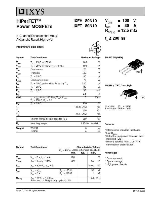
HiPerFETTM Power MOSFETs
N-Channel Enhancement Mode Avalanche Rated, High dv/dt
Preliminary data sheet
IXFH 80N10 IXFT 80N10
VDSS = 100 V ID25 = 80 A RDS(on) = 12.5 mΩ
trr ≤ 200 ns
Symbol VDSS VDGR VGS VGSM I
D25
I
L(RMS)
I
DM
IAR EAR EAS dv/dt
P D
T J
TJM Tstg TL Md Weight
Symbol
VDSS VGS(th) IGSS IDSS
RDS(on)
Test Conditions
TJ = 25°C to 150°C TJ = 25°C to 150°C; RGS = 1 MΩ Continuous
Transient
T C
= 25°C
Lead current limit
T C
=
25°C,
pulse
width
limited
by
T JM
TC = 25°C
TC = 25°C
IS ≤ IDM, di/dt ≤ 100 A/µs, VDD ≤ VDSS,
T J
≤
150°C,
R G
=
2
Ω
T C
= 25°C
1.6 mm (0.063 in) from case for 10 s
Mounting torque
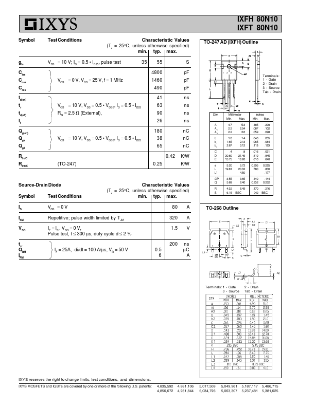
TO-247 TO-268
Maximum Ratings
100 100 ±20 ±30 80 75 320 80 50 2.
 80N10 Datasheet