Click to expand full text
XC6190 Series
ETR02031-003
Push Button Reboot Controller
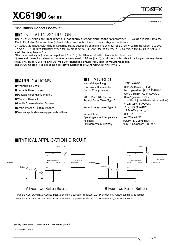
■GENERAL DESCRIPTION
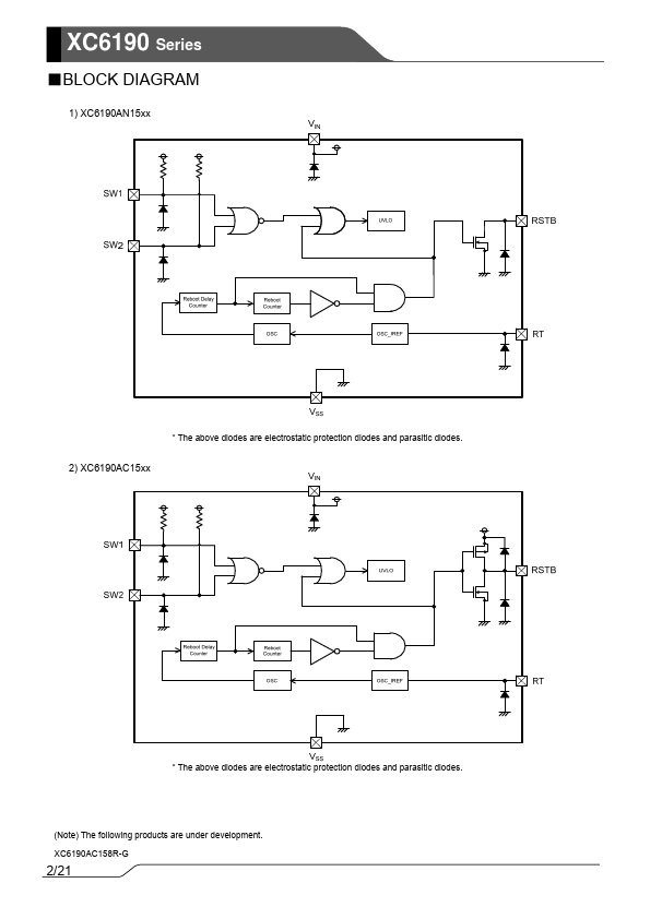
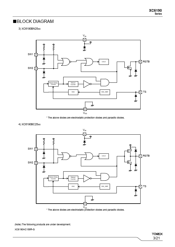
The XC6190 series are timer reset ICs that supply a reboot signal to the system when “L” voltage is input into the SW1, SW2 pins for a set time (reboot delay time) using two switches (physical buttons).
On type A, the reboot delay time (TDL) can be set as desired by changing the external resistance RT within the range 1s to 20s. On type B, TDL is fixed internally. When the TS pin is set to “H” level, the delay time is 12.5s. When the TS pin is set to “L” level, the delay time is 7.5s. After the reboot signal (TRSTB) is output for 0.4s (TYP), the IC automatically returns to the steady state.
Quiescent current in standby mode is a very small 0.01μA (TYP.), and this contributes to a longer battery drive time.
 XC6190 Datasheet