ST2317DFX
DESCRIPTION
The device is manufactured using Diffused Collector technology for more stable operation Vs base drive circuit variations resulting in very low worst case dissipation.
ISOWATT218FX
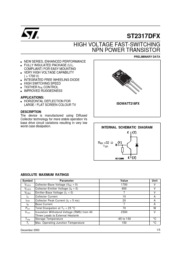
INTERNAL SCHEMATIC DIAGRAM
RBE =32 Ω
Typ.
ABSOLUTE MAXIMUM RATINGS
Symbol V CES V CEO V EBO IC I CM IB P tot V isol T stg Tj Parameter Collector-Base Voltage (V BE = 0) Collector-Emitter Voltage (I B = 0) Emitter-Base Voltage (I C = 0) Collector Current Collector Peak Current (t p < 5 ms) Base Current Total Dissipation at T C = 25 o C Insulation Withstand Voltage (RMS) from All Three Leads to External Heatsink Storage Temperature Max. Operating Junction Temperature Value 1700 600 7 10 20 7 70 2500 -65 to 150 150 Unit V V V A A A W V o o
C C 1/5
December 2003
THERMAL DATA
R thj-case Thermal Resistance Junction-case Max 1.8 o
C/W
ELECTRICAL CHARACTERISTICS (Tcase = 25 o C unless otherwise specified)
Symbol I CES I EBO V (BR)EBO Parameter Collector Cut-off Current (V BE = 0)...