ST2310HI
DESCRIPTION
The device is manufactured using Diffused Collector technology for more stable operation Vs base drive circuit variations resulting in very low worst case dissipation.
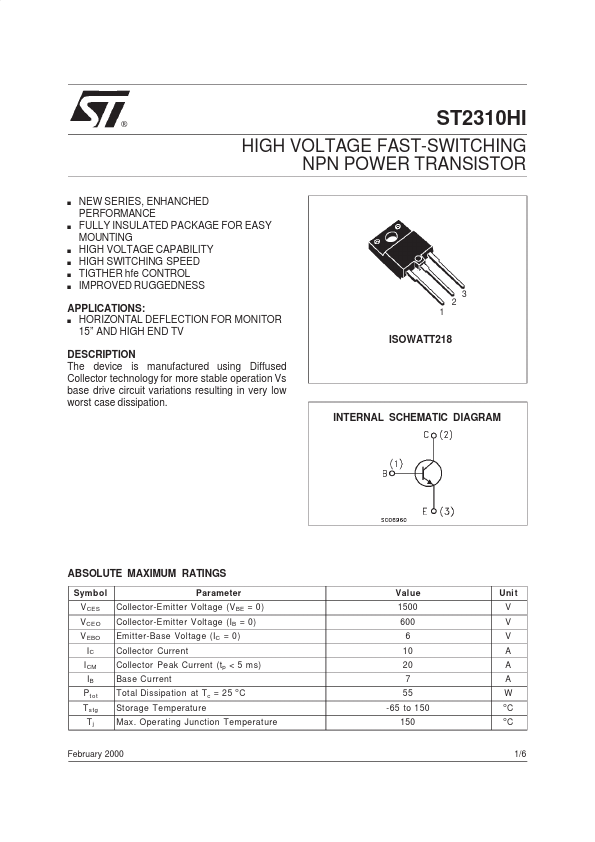
ISOWATT218
INTERNAL SCHEMATIC DIAGRAM
ABSOLUTE MAXIMUM RATINGS
Symbol V CES V CEO V EBO IC I CM IB P t ot T stg Tj Parameter Collector-Emitter Voltage (V BE = 0) Collector-Emitter Voltage (IB = 0) Emitter-Base Voltage (IC = 0) Collector Current Collector Peak Current (tp < 5 ms) Base Current Total Dissipation at Tc = 25 o C St orage Temperature Max. Operating Junction Temperature Value 1500 600 6 10 20 7 55 -65 to 150 150 Uni t V V V A A A W o o
February 2000
1/6
THERMAL DATA
R t hj-ca se Thermal Resistance Junction-case Max 2.3 o
C/W
ELECTRICAL CHARACTERISTICS (Tcase = 25 o C unless otherwise specified)
Symb ol I CES I EBO Parameter Collector Cut-off Current (V BE = 0) Emitter Cut-off Current (I C = 0) Test Cond ition s V CE = 1500 V V EB = 7 V I C = 100 m A L = 25 m H 600 Min. Typ . Max....