PIN NUMBER 1
SYMBOL SDA
2
GND
3
VCC
4
A1
5
A0
6
RH
7
RW
8
RL
9
V+
10
SCL
DESCRIPTION Data I/O for I2C serial interface; it has an open drain output and may be wire-or’d with other open drain active low outputs
Ground
Positive logic supply voltage Address select pin used to set t
Key Features
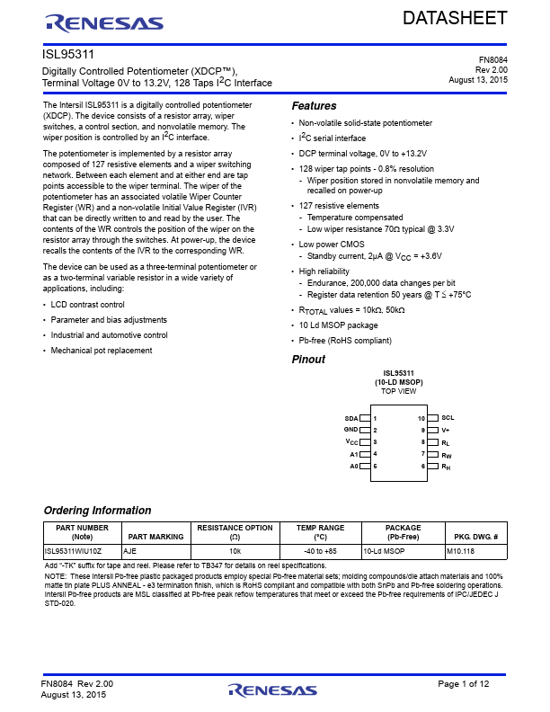
Non-volatile solid-state potentiometer.
I2C serial interface.
DCP terminal voltage, 0V to +13.2V.
128 wiper tap points - 0.8% resolution - Wiper position stored in nonvolatile memory and recalled on power-up.
127 resistive elements - Temperature compensated - Low wiper resistance 70 typical @ 3.3V.
Full PDF Text Transcription for ISL95311 (Reference)
Note: Below is a high-fidelity text extraction (approx. 800 characters) for
ISL95311. For precise diagrams, and layout, please refer to the original PDF.
DATASHEET ISL95311 Digitally Controlled Potentiometer (XDCP™), Terminal Voltage 0V to 13.2V, 128 Taps I2C Interface The Intersil ISL95311 is a digitally controlled potent...
View more extracted text
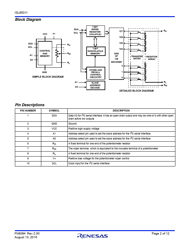
s I2C Interface The Intersil ISL95311 is a digitally controlled potentiometer (XDCP). The device consists of a resistor array, wiper switches, a control section, and nonvolatile memory. The wiper position is controlled by an I2C interface. The potentiometer is implemented by a resistor array composed of 127 resistive elements and a wiper switching network. Between each element and at either end are tap points accessible to the wiper terminal. The wiper of the potentiometer has an associated volatile Wiper Counter Register (WR) and a non-volatile Initial Value Register (IVR) that can be directly written to and read by the u
 ISL95311 Datasheet