Click to expand full text
DATASHEET
HIP4020
Half Amp Full Bridge Power Driver for Small 3V, 5V, and 12V DC Motors
FN3976 Rev.5.00 Feb 8, 2019
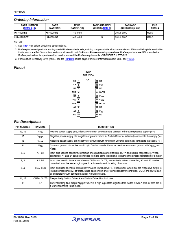
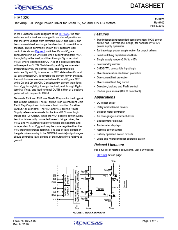
In the Functional Block Diagram of the HIP4020, the four switches and a load are arranged in an H-configuration so that the drive voltage from terminals OUTA and OUTB can be cross-switched to change the direction of current flow in the load. This is commonly known as 4-quadrant load control. As shown Figure 1, switches Q1 and Q4 are conducting or in an ON state when current flows from VDD through Q1 to the load, and then through Q4 to terminal VSSB; where load terminal OUTA is at a positive potential with respect to OUTB. Switches Q1 and Q4 are operated synchronously by the control logic.
 HIP4020 Datasheet