Download the MC100E241 datasheet PDF.
This datasheet also covers the MC10E241 variant, as both devices belong to the same 8-bit scannable register family and are provided as variant models within a single manufacturer datasheet.
Key Features
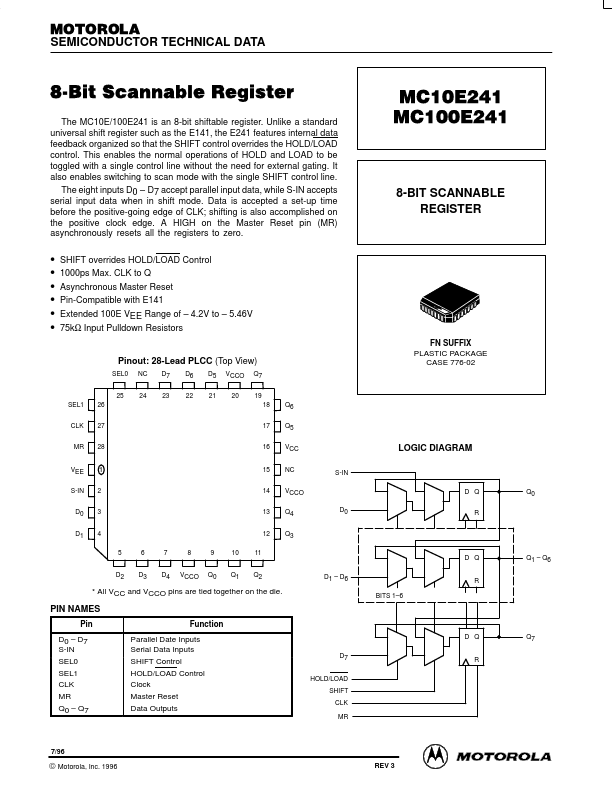
internal data feedback organized so that the SHIFT control overrides the HOLD/LOAD control. This enables the normal operations of HOLD and LOAD to be toggled with a single control line without the need for external gating. It also enables switching to scan mode with the single SHIFT control line. The eight inputs D0.
D7 accept parallel input data, while S-IN accepts serial input data when in shift mode. Data is accepted a set-up time before the positive-going edge of CLK; shifting is al.
Full PDF Text Transcription for MC100E241 (Reference)
Note: Below is a high-fidelity text extraction (approx. 800 characters) for
MC100E241. For precise diagrams, and layout, please refer to the original PDF.
MOTOROLA SEMICONDUCTOR TECHNICAL DATA 8ĆBit Scannable Register The MC10E/100E241 is an 8-bit shiftable register. Unlike a standard universal shift register such as the E1...
View more extracted text
le register. Unlike a standard universal shift register such as the E141, the E241 features internal data feedback organized so that the SHIFT control overrides the HOLD/LOAD control. This enables the normal operations of HOLD and LOAD to be toggled with a single control line without the need for external gating. It also enables switching to scan mode with the single SHIFT control line. The eight inputs D0 – D7 accept parallel input data, while S-IN accepts serial input data when in shift mode. Data is accepted a set-up time before the positive-going edge of CLK; shifting is also accomplished on the positive clock edge.
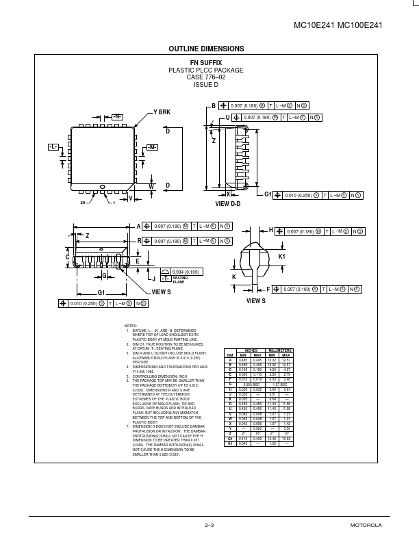
 MC100E241 Datasheet