74LS112A
features individual J, K, clock, and asynchronous set and clear inputs to each flip-flop. When the clock goes HIGH, the inputs are enabled and data will be accepted. The logic level of the J and K inputs may be allowed to change when the clock pulse is HIGH and the bistable will perform according to the truth table as long as minimum set-up and hold time are observed. Input data is transferred to the outputs on the negative-going edge of the clock pulse.
SN54/74LS112A
DUAL JK NEGATIVE EDGE-TRIGGERED FLIP-FLOP
LOW POWER SCHOTTKY
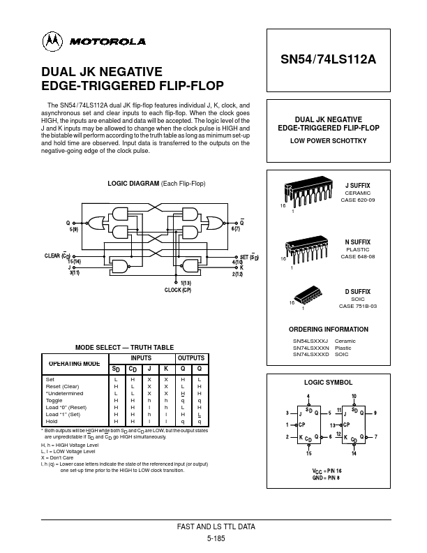
LOGIC DIAGRAM (Each Flip-Flop)
Q 5(9)
CLEAR (CD) 15(14) J 3(11)
1(13) CLOCK (CP)
MODE SELECT
- TRUTH TABLE
OPERATING MODE
Set Reset (Clear)
- Undetermined Toggle Load “0” (Reset) Load “1” (Set) Hold
INPUTS
SD CD
LH HL LL HH HH HH HH
X X X h l h l
OUTPUTS
XHL XLH XHH hqq h LH l HL l qq
- Both outputs will be HIGH while both SD and CD are LOW, but the output...