Datasheet4U Logo Datasheet4U.com

X9C503 - Digitally Controlled Potentiometer

Download the X9C503 datasheet PDF. This datasheet also covers the X9C102 variant, as both devices belong to the same digitally controlled potentiometer family and are provided as variant models within a single manufacturer datasheet.

Features

  • Solid-State Potentiometer.
  • Three-Wire Serial Interface.
  • 100 Wiper Tap Points - Wiper Position Stored in Non-volatile Memory and Recalled on Power-up.
  • 99 Resistive Elements - Temperature Compensated - End-to-End Resistance, ±20% - Terminal Voltages, ±5V.
  • Low Power CMOS - VCC = 5V - Active Current, 3mA max. - Standby Current, 750µA max.
  • High Reliability - Endurance, 100,000 Data Changes per Bit - Register Data Retention, 100 years.
  • X.

📥 Download Datasheet

Note: The manufacturer provides a single datasheet file (X9C102-Intersil.pdf) that lists specifications for multiple related part numbers.

Full PDF Text Transcription

Click to expand full text
® Data Sheet X9C102, X9C103, X9C104, X9C503 July 20, 2009 FN8222.3 Digitally Controlled Potentiometer (XDCP™) 
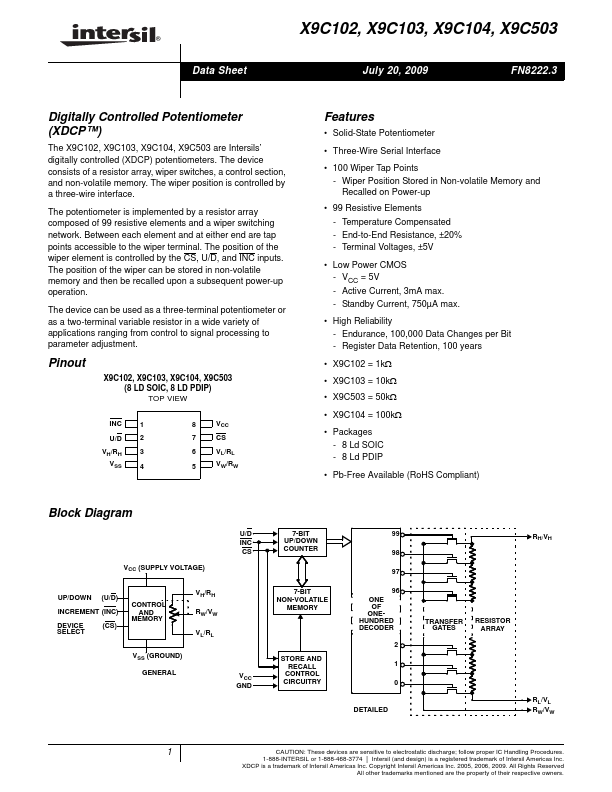
The X9C102, X9C103, X9C104, X9C503 are Intersils’ digitally controlled (XDCP) potentiometers. The device consists of a resistor array, wiper switches, a control section, and non-volatile memory. The wiper position is controlled by a three-wire interface. The potentiometer is implemented by a resistor array composed of 99 resistive elements and a wiper switching network. Between each element and at either end are tap points accessible to the wiper terminal. The position of the wiper element is controlled by the CS, U/D, and INC inputs. The position of the wiper can be stored in non-volatile memory and then be recalled upon a subsequent power-up operation.
Published: |