Datasheet4U Logo Datasheet4U.com

IC-706MKIIG - HF/VHF/UHF ALL MODE TRANSCEVER Service Manual

Description

Used RF high-pass filter (HPF board) Frequency Control Entrance Frequency Control Entrance (MHz) signal signal coil coil (MHz) 0.03 2 MHz 2 4 MHz 4 8 MHz 8 15 MHz THH L2H L3H L4H D111 D121 D131 D141 15 22 MHz 22 30 MHz 30 40 MHz 40

Features

  • sired band signals and suppress any undesired band signals. The HF/50 MHz RF circuit has 7 low-pass filters and 8 high-pass filters for specified band use. HF/50 MHz RF signals from the [ANT1] connector, pass through one of 7 low-pass filters as below, the transmit/ receive switching relay (FILTER board; RL1) and low-pass filter (FILTER board; L1, L2, C1.
  • C5), and are then applied to th.

📥 Download Datasheet

Datasheet Details

Part number IC-706MKIIG
Manufacturer Icom
File Size 10.25 MB
Description HF/VHF/UHF ALL MODE TRANSCEVER Service Manual
Datasheet download datasheet IC-706MKIIG Datasheet

Full PDF Text Transcription

Click to expand full text
HF/VHF/UHF ALL MODE TRANSCEVER S-14411XZ-C1 June. 2007 INTRODUCTION 
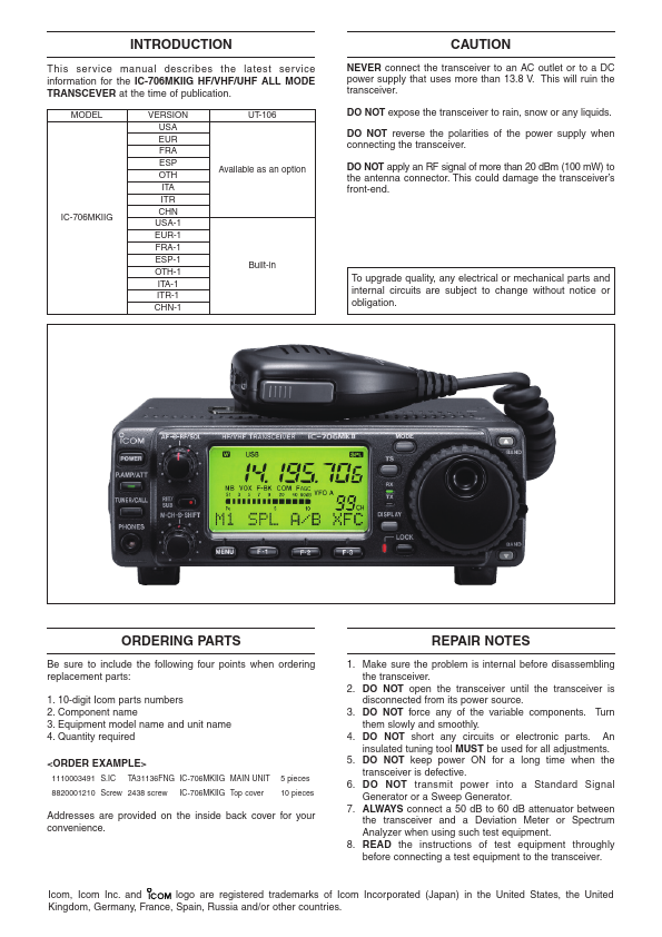
This service manual describes the latest service information for the IC-706MKIIG HF/VHF/UHF ALL MODE TRANSCEVER at the time of publication. MODEL VERSION USA EUR FRA ESP OTH ITA ITR CHN USA-1 EUR-1 FRA-1 ESP-1 OTH-1 ITA-1 ITR-1 CHN-1 UT-106 CAUTION NEVER connect the transceiver to an AC outlet or to a DC power supply that uses more than 13.8 V. This will ruin the transceiver. DO NOT expose the transceiver to rain, snow or any liquids. DO NOT reverse the polarities of the power supply when connecting the transceiver. Available as an option DO NOT apply an RF signal of more than 20 dBm (100 mW) to the antenna connector. This could damage the transceiver’s front-end.
Published: |