Click to expand full text
Advance Technical Information
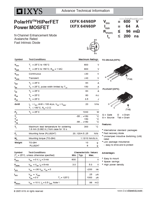
PolarHV HiPerFET Power MOSFET
TM
IXFK 64N60P IXFX 64N60P
N-Channel Enhancement Mode Avalanche Rated Fast Intrinsic Diode
RDS(on) trr
VDSS ID25
= 600 V = 64 A ≤ 96 mΩ ≤ 200 ns
www.DataSheet4U.com
Symbol VDSS VDGR VGSS VGSM ID25 IDM IAR EAR EAS dv/dt PD TJ TJM Tstg TL FC Md Weight
Test Conditions TJ = 25°C to 150°C TJ = 25°C to 150°C; RGS = 1 MΩ Continuous Transient TC = 25°C TC = 25°C, pulse width limited by TJM TC = 25°C TC = 25°C TC = 25°C IS ≤ IDM, di/dt ≤ 100 A/µs, VDD ≤ VDSS, TJ ≤ 150°C, RG = 2 Ω TC = 25°C
Maximum Ratings 600 600 ± 30 ± 40 64 150 64 80 3.5 20 1040 -55 ... +150 150 -55 ...
 IXFX64N60P Datasheet