Datasheet4U Logo Datasheet4U.com

IXFK180N25T - GigaMOS Power MOSFET

Download the IXFK180N25T datasheet PDF. This datasheet also covers the IXFX180N25T variant, as both devices belong to the same gigamos power mosfet family and are provided as variant models within a single manufacturer datasheet.

Features

  • z z z z z 1.6mm (0.062 in. ) from Case for 10s Plastic Body for 10s Mounting Torque (TO-264) Mounting Force TO-264 PLUS247 (PLUS247) 300 260 1.13/10 20..120 /4.5..27 10 6 International Standard Packages High Current Handling Capability Fast Intrinsic Diode Avalanche Rated Low RDS(on) Advantages z Symbol Test Conditions (TJ = 25°C Unless Otherwise Specified) BVDSS VGS(th) IGSS IDSS RDS(on) VGS = 0V, ID = 3mA VDS = VGS, ID = 8mA VGS = ± 20V, VDS = 0V VDS = VDSS, VGS= 0V VGS = 10V, ID = 60A, No.

📥 Download Datasheet

Note: The manufacturer provides a single datasheet file (IXFX180N25T_IXYS.pdf) that lists specifications for multiple related part numbers.

Full PDF Text Transcription

Click to expand full text
Advance Technical Information www.DataSheet4U.com GigaMOSTM Power MOSFET N-Channel Enhancement Mode Avalanche Rated Fast Intrinsic Diode IXFK180N25T IXFX180N25T RDS(on) ≤ ≤ trr TO-264 (IXFK) VDSS ID25 = = 250V 180A 12.9mΩ 200ns 
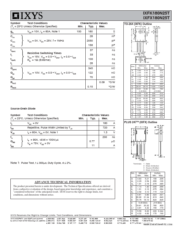
Symbol VDSS VDGR VGSS VGSM ID25 IL(RMS) IDM IA EAS dV/dt PD TJ TJM Tstg TL TSOLD Md FC Weight Test Conditions TJ = 25°C to 150°C TJ = 25°C to 150°C, RGS = 1MΩ Continuous Transient TC = 25°C External Lead Current Limit TC = 25°C, Pulse Width Limited by TJM TC = 25°C TC = 25°C IS ≤ IDM, VDD ≤ VDSS, TJ ≤ 150°C TC = 25°C Maximum Ratings 250 250 ± 20 ± 30 180 160 500 40 3 20 1390 -55 ... +150 150 -55 ... +150 V V V V A A A A J V/ns W °C °C °C °C °C Nm/lb.in. N/lb.
Published: |