Click to expand full text
HD74ALVCH162827
20-bit Buffers / Drivers with 3-state Outputs
ADE-205-188B (Z) 3rd. Edition December 1999 Description
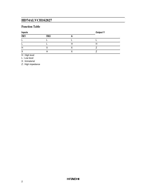
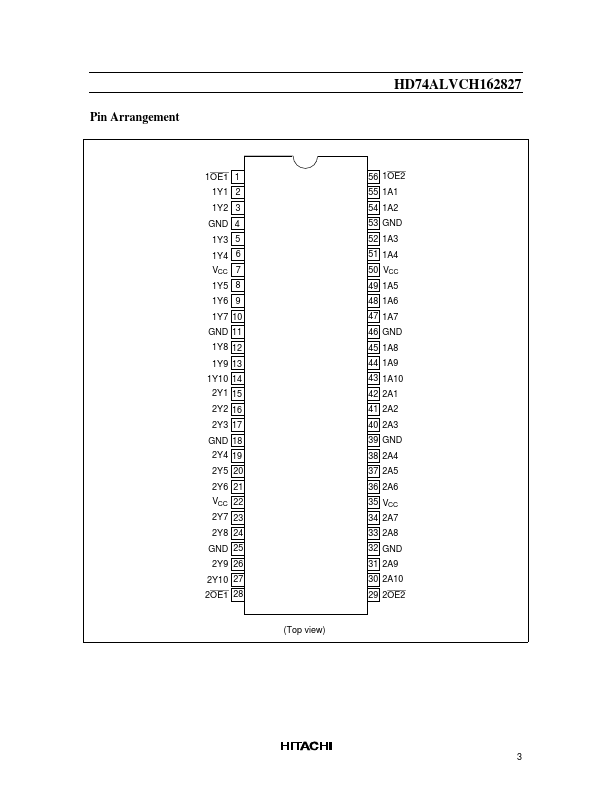
The HD74ALVCH162827 is composed of two 10-bit sections with separate output enable signals. For either 10-bit buffer section, the two output enable (1OE1 and 1OE2 or 2OE1 and 2OE2) inputs must both be low for the corresponding Y outputs to be active. If either output enable input is high, the outputs of that 10-bit buffer section are in the high impedance state. Active bus hold circuitry is provided to hold unused or floating data inputs at a valid logic level. All outputs, which are designed to sink up to 12 mA, include 26 Ω resistors to reduce overshoot and undershoot.
Features
• VCC = 2.3 V to 3.6 V • Typical VOL ground bounce < 0.8 V (@VCC = 3.
 HD74ALVCH162827 Datasheet