Click to expand full text
Data Sheet
FEATURES
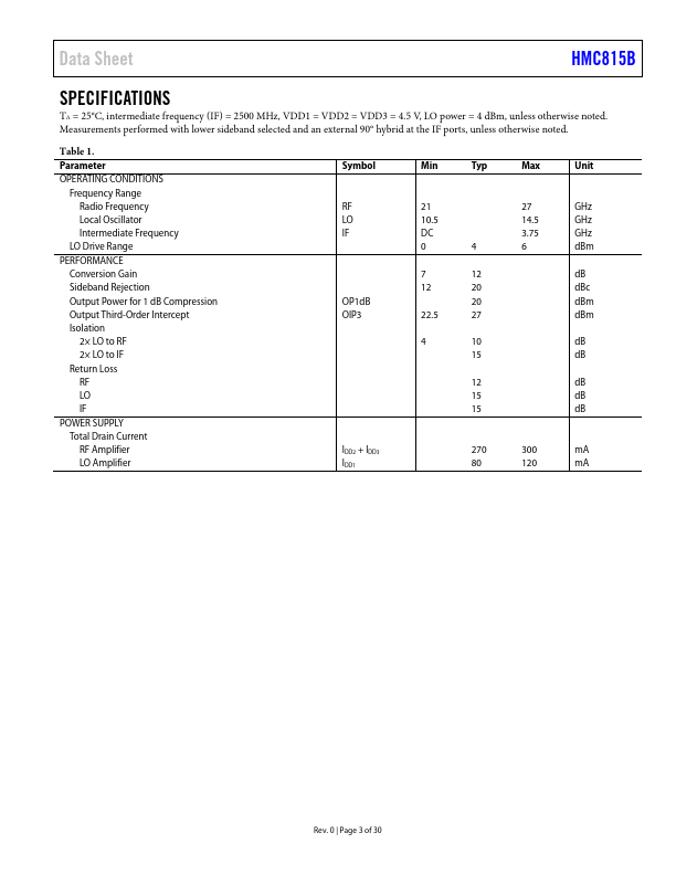
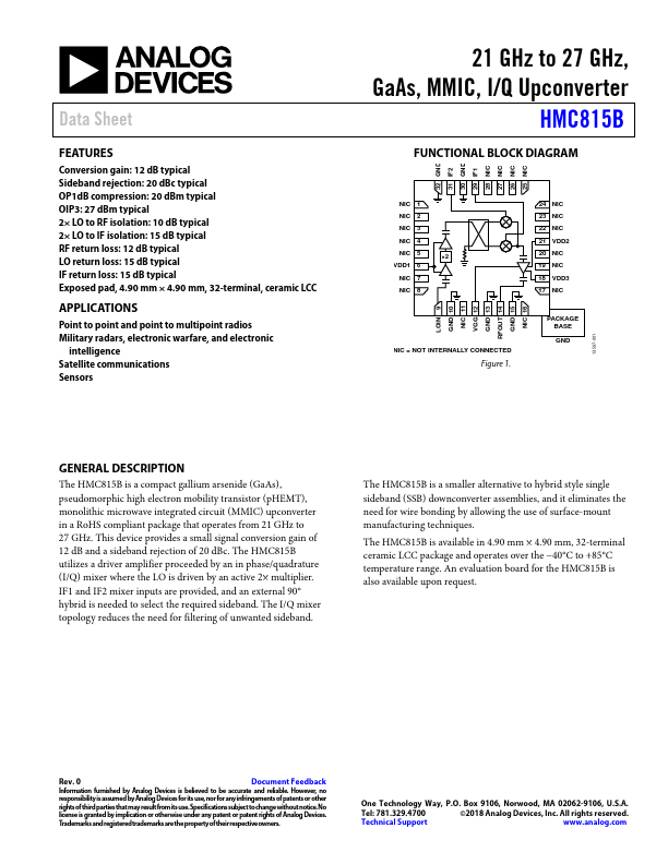
Conversion gain: 12 dB typical Sideband rejection: 20 dBc typical OP1dB compression: 20 dBm typical OIP3: 27 dBm typical 2× LO to RF isolation: 10 dB typical 2× LO to IF isolation: 15 dB typical RF return loss: 12 dB typical LO return loss: 15 dB typical IF return loss: 15 dB typical Exposed pad, 4.90 mm × 4.90 mm, 32-terminal, ceramic LCC
APPLICATIONS
Point to point and point to multipoint radios Military radars, electronic warfare, and electronic
intelligence Satellite communications Sensors
21 GHz to 27 GHz, GaAs, MMIC, I/Q Upconverter
HMC815B
FUNCTIONAL BLOCK DIAGRAM
32 GND 31 IF2 30 GND 29 IF1 28 NIC 27 NIC 26 NIC 25 NIC
NIC 1
NIC 2
NIC 3
NIC 4
NIC 5
×2
VDD1 6
NIC 7
NIC 8
NIC = NOT INTERNALLY CONNECTED
Figure 1.
 HMC815B Datasheet