Datasheet Details
| Part number | NIMD6001AN, NIMD6001N |
|---|---|
| Manufacturer | ON Semiconductor ↗ |
| File Size | 198.79 KB |
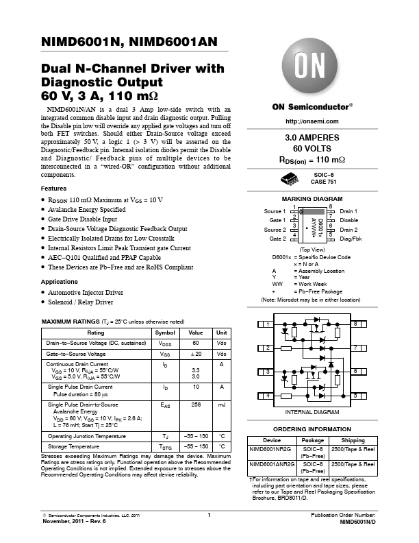
| Description | Dual N-Channel Driver |
| Datasheet |
 NIMD6001N-ONSemiconductor.pdf NIMD6001N-ONSemiconductor.pdf
|
| Note |
This datasheet PDF includes multiple part numbers: NIMD6001AN, NIMD6001N. Please refer to the document for exact specifications by model. |