Datasheet Details
| Part number | MAX14806 |
|---|---|
| Manufacturer | Maxim Integrated (Analog Devices) |
| File Size | 1.12 MB |
| Description | High-Voltage Analog Switches |
| Datasheet |
 MAX14806 Datasheet MAX14806 Datasheet
|
|
|
Download the MAX14806 datasheet PDF. This datasheet also covers the MAX14805 variant, as both devices belong to the same high-voltage analog switches family and are provided as variant models within a single manufacturer datasheet.
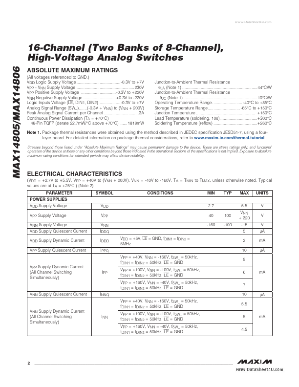
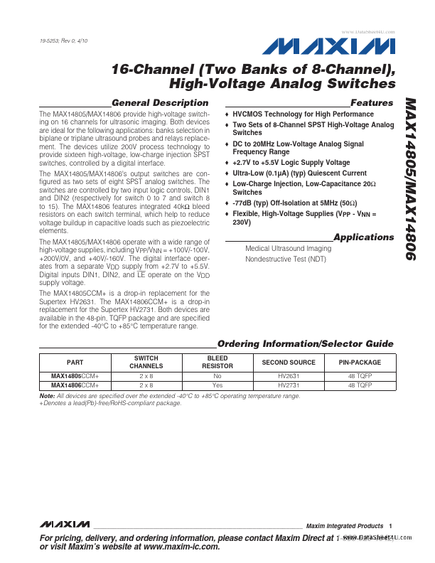
The MAX14805/MAX14806 provide high-voltage switching on 16 channels for ultrasonic imaging.
Both devices are ideal for the following applications: banks selection in biplane or triplane ultrasound probes and relays replacement.
| Part number | MAX14806 |
|---|---|
| Manufacturer | Maxim Integrated (Analog Devices) |
| File Size | 1.12 MB |
| Description | High-Voltage Analog Switches |
| Datasheet |
MAX14806 Datasheet
|
|
|
|
| Part Number | Description | Manufacturer |
|---|---|---|
| MAX14803A | High-Voltage Analog Switches | Maxim Integrated |
| MAX14808 | Octal Three-Level/Quad Five-Level High-Voltage 2A Digital Pulsers | Maxim Integrated |
| MAX14809 | Octal Three-Level/Quad Five-Level High-Voltage 2A Digital Pulsers | Maxim Integrated |
| MAX1480A | Complete / Isolated RS-485/RS-422 Data Interface | Maxim Integrated |
| MAX1480C | Complete / Isolated RS-485/RS-422 Data Interface | Maxim Integrated |
| Part Number | Description |
|---|---|
| MAX14800 | High-Voltage Analog Switches |
| MAX14801 | High-Voltage Analog Switches |
| MAX14802 | High-Voltage Analog Switches |
| MAX14803 | High-Voltage Analog Switches |
| MAX14805 | High-Voltage Analog Switches |
The following content is an automatically extracted verbatim text from the original manufacturer datasheet and is provided for reference purposes only.