Datasheet Details
| Part number | PGA116 |
|---|---|
| Manufacturer | Texas Instruments |
| File Size | 2.20 MB |
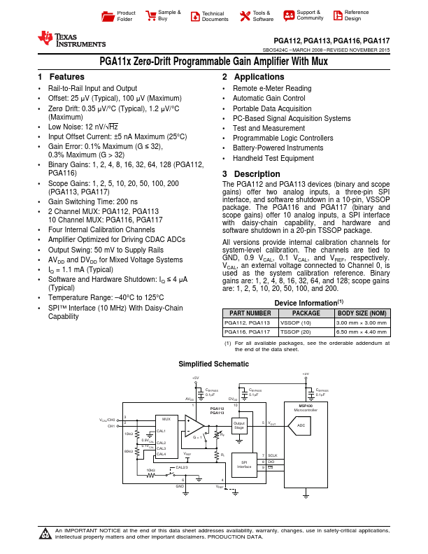
| Description | Zero-Drift Programmable Gain Amplifier |
| Datasheet |
 PGA116 Datasheet PGA116 Datasheet
|
|
|
Download the PGA116 datasheet PDF (PGA112 included). The manufacturer datasheet provides complete specifications, pinout details, electrical characteristics, and typical applications for zero-drift programmable gain amplifier.
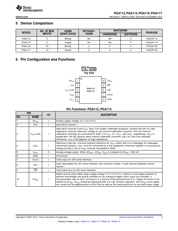
The PGA112 and PGA113 devices (binary and scope gains) offer two analog inputs, a three-pin SPI interface, and software shutdown in a 10-pin, VSSOP package.
| Part number | PGA116 |
|---|---|
| Manufacturer | Texas Instruments |
| File Size | 2.20 MB |
| Description | Zero-Drift Programmable Gain Amplifier |
| Datasheet |
PGA116 Datasheet
|
|
|
|