The following content is an automatically extracted verbatim text
from the original manufacturer datasheet and is provided for reference purposes only.
View original datasheet text
SN54HC109, SN74HC109
SCLS470C – MARCH 2003 – REVISED JUNE 2022
SNx4HC109 Dual J-K Positive-Edge-Triggered Flip-Flops With Clear and Preset
1 Features
• Wide operating voltage range of 2 V to 6 V • Low input current of 1 μA max • High-current outputs drive up to 10 LSTTL loads • Low power consumption, 40-μA max ICC • Typical tpd = 12 ns • ±4-mA output drive at 5 V
2 Description
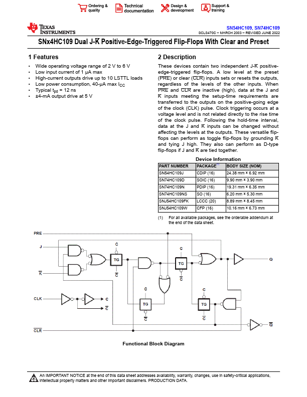
These devices contain two independent J-K positiveedge-triggered flip-flops. A low level at the preset (PRE) or clear (CLR) inputs sets or resets the outputs, regardless of the levels of the other inputs. When PRE and CLR are inactive (high), data at the J and K inputs meeting the setup-time requirements are transferred to the outputs on the positive-going edge of the clock (CLK) pulse.
 74HC109 Datasheet

