PL671-06 Description
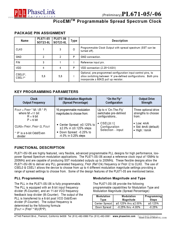
The PL671-05 and -06 are advanced programmable clock and Spread Spectrum clock generators (PSSCG), and members of PhaseLink’s PicoPLL™ Programmable Clock family. The PL671-05 and -06 offer up to 200MHz outputs, and allow for programming the modulation type (center or down Spread), as well as 16 modulation magnitudes (±0.125 to ±2.0% or -0.25 to -4.0%) to choose from. In addition, the CSEL[0:1] pins can be used to...
PL671-06 Key Features
- Advanced programmable PLL with Spread Spectrum
- Accepts reference clock input: 10-200MHz
- Output frequency range: up to 166MHz @ 2.5V or up to 200MHz @ 3.3V operation
- Programmable Spread Spectrum modulation magnitude: o Center Spread: ±0.125% to ±2.0% in ±0.125% steps o Down Spread: -0.
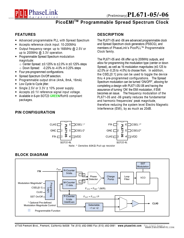
- Four pre-programmed configurations
- Spread Spectrum On/Off selection
- Programmable output drive (4mA, 8mA, 16mA)
- Low Cycle to Cycle jitter
- Single 2.5V or 3.3V ± 10% power supply
- Accepts ≥0.1V reference signal input voltage