26 V, IDQ = 450 mA, Pout = 60 W PEP f MHz 930 945 960 Zsource Ω 0.80.
j0.10 0.80.
j0.05 0.81.
j0.10 Zload Ω 2.08.
j0.65 2.07.
j0.38 2.04.
j0.37
Zsource = Test circuit impedance as measured from gate to ground. Zload = Test circuit impedance as measured from drain to ground. Device Under Test Output Matching Network
Input Matching Network
Z
source
Z
load
Figure 9. Series Equivalent Source and Load Impedance
MRF9060LR1 MRF9060LSR1 5.
Full PDF Text Transcription for MRF9060LR1 (Reference)
Note: Below is a high-fidelity text extraction (approx. 800 characters) for
MRF9060LR1. For precise diagrams, tables, and layout, please refer to the original PDF.
View original datasheet text
Freescale Semiconductor Technical Data
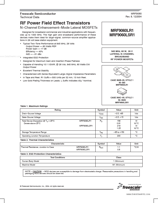
MRF9060 Rev. 8, 12/2004
RF Power Field Effect Transistors
N−Channel Enhancement−Mode Lateral MOSFETs
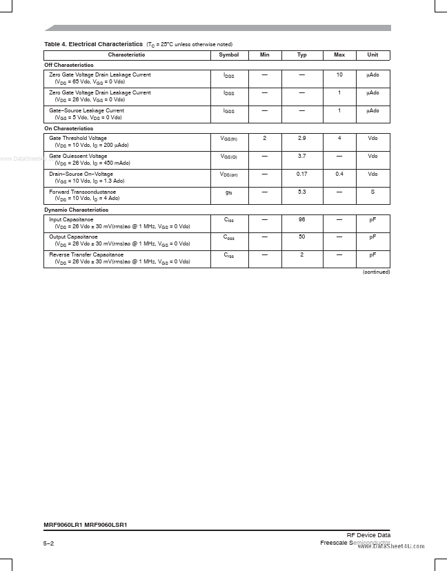
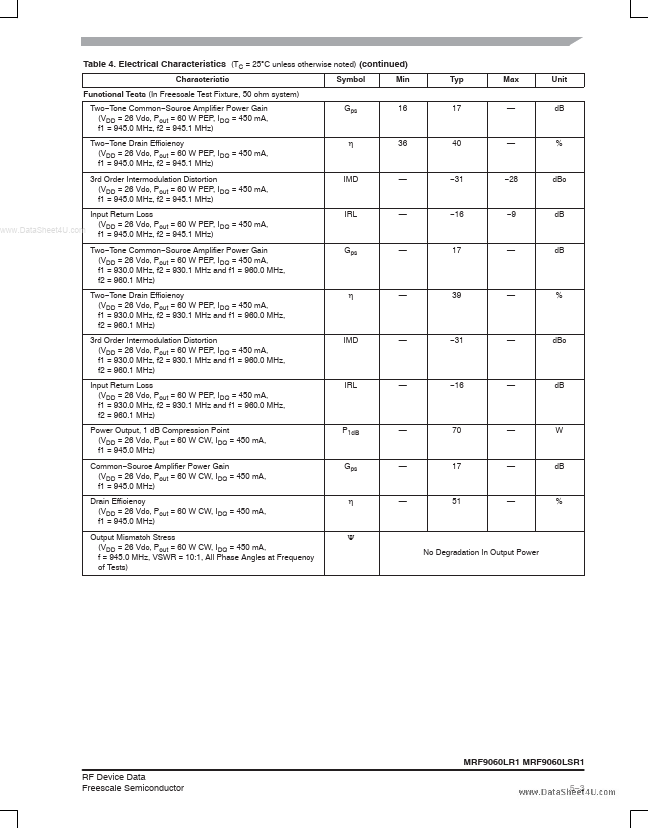
Designed for broadband commercial and industrial applications with frequencies up to 1000 MHz. The high gain and broadband performance of these devices make them ideal for large−signal, common−source amplifier applications in 26 volt base station equipment. • Typical Two−Tone Performance at 945 MHz, 26 Volts Output Power — 60 Watts PEP Power Gain — 17 dB Efficiency — 40% IMD — −31 dBc
www.DataSheet4U.
 MRF9060LR1 Datasheet