Datasheet4U Logo Datasheet4U.com

SN74SSQEC32882 - 28-Bit to 56-Bit Registered Buffer

Datasheet Summary

Description

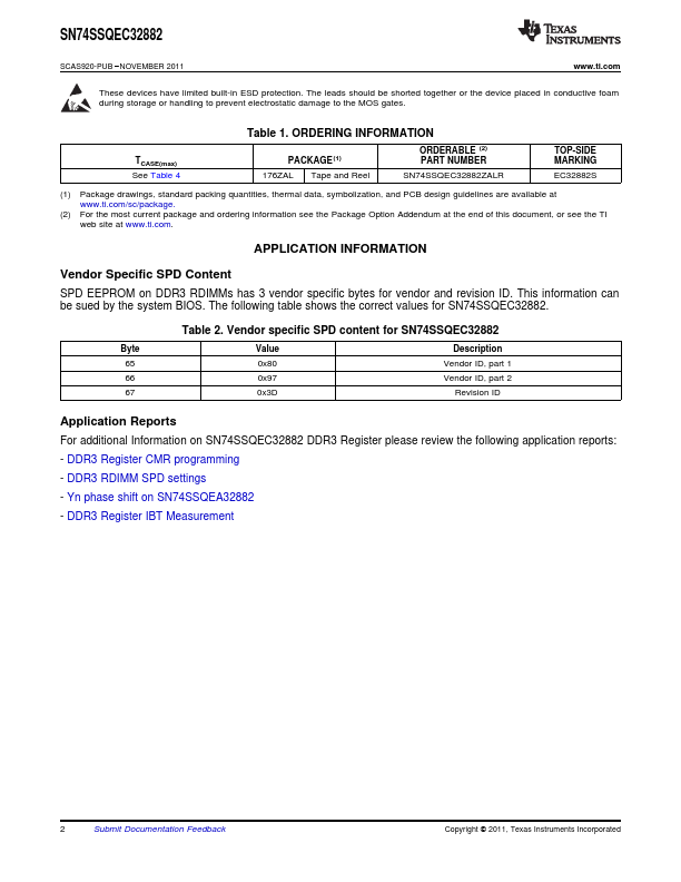
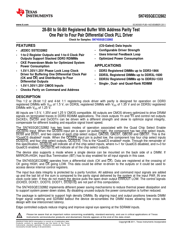
This 1:2 or 26-bit 1:2 and 4-bit 1:1 registering clock driver with parity is designed for operation on DDR3 registered DIMMs with VDD of 1.5 V, on DDR3L registered DIMMs with VDD of 1.35 V and on DDR3U registered DIMMs with VDD of 1.25 V.

All inputs are 1.5 V, 1.35V and 1.25 V CMOS compatible.

Features

  • 1.
  • JEDEC SSTE32882.
  • 1-to-2 Register Outputs and 1-to-4 Clock Pair Outputs Support Stacked DDR3 RDIMMs.
  • CKE Powerdown Mode for Optimized System Power Consumption.
  • 1.5V/1.35V/1.25V Phase Lock Loop Clock Driver for Buffering One Differential Clock Pair (CK and CK) and Distributing to Four Differential Outputs.
  • 1.5V/1.35V/1.25V CMOS Inputs.
  • Checks Parity on Command and Address (CS-Gated) Data Inputs.
  • Configurable Driver Strength.

📥 Download Datasheet

Datasheet preview – SN74SSQEC32882

Datasheet Details

Part number SN74SSQEC32882
Manufacturer Texas Instruments
File Size 767.61 KB
Description 28-Bit to 56-Bit Registered Buffer
Datasheet download datasheet SN74SSQEC32882 Datasheet
Additional preview pages of the SN74SSQEC32882 datasheet.
Other Datasheets by Texas Instruments

Full PDF Text Transcription

Click to expand full text
SN74SSQEC32882 www.ti.com SCAS920-PUB – NOVEMBER 2011 28-Bit to 56-Bit Registered Buffer With Address Parity Test One Pair to Four Pair Differential Clock PLL Driver Check for Samples: SN74SSQEC32882 FEATURES 1 • JEDEC SSTE32882 • 1-to-2 Register Outputs and 1-to-4 Clock Pair Outputs Support Stacked DDR3 RDIMMs • CKE Powerdown Mode for Optimized System Power Consumption • 1.5V/1.35V/1.25V Phase Lock Loop Clock Driver for Buffering One Differential Clock Pair (CK and CK) and Distributing to Four Differential Outputs • 1.5V/1.35V/1.
Published: |