Datasheet Details
| Part number | CHP1102-98F |
|---|---|
| Manufacturer | United Monolithic Semiconductors |
| File Size | 947.07 KB |
| Description | S-Band 6-bit Phase Shifter |
| Datasheet |
 CHP1102-98F Datasheet CHP1102-98F Datasheet
|
|
|
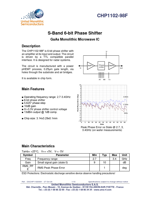
an amplifier at its input and output.
interface.
It is designed for radar systems.
| Part number | CHP1102-98F |
|---|---|
| Manufacturer | United Monolithic Semiconductors |
| File Size | 947.07 KB |
| Description | S-Band 6-bit Phase Shifter |
| Datasheet |
CHP1102-98F Datasheet
|
|
|
|