U210B
Features
D Externally controlled integrated amplifier D Variable soft start D Automatic retriggering D Voltage and current synchronisation D Triggering pulse typ. 125 m A D Internal supply voltage monitoring D Temperature constant reference source D Current requirement ≤ 3 m A
Case: DIP 14, SO 16
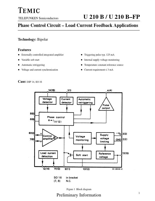
Figure 1 Block diagram
Preliminary Information
U 210 B / U 210 B- FP
TELEFUNKEN Semiconductors
Figure 2 Block diagram with external circuitry Open loop control with load current pensation 2
Preliminary Information
TELEFUNKEN Semiconductors
U 210 B / U 210 B- FP
Description
Mains supply
The U 210 B is fitted with voltage limiting and can therefore be supplied directly from the mains. The supply voltage between Pin 2 (+pol/ă) and Pin 3 builds up across D1 and R1 and is smoothed by C1. The va Iue of the series resistance can be approximated using: R1= VM- VS 2 IS
Further information regarding the design of the mains supply can be found in the data sheets in the appendix. The reference...