Datasheet Details
| Part number | CXD1807Q |
|---|---|
| Manufacturer | Sony Semiconductor Solutions |
| File Size | 255.25 KB |
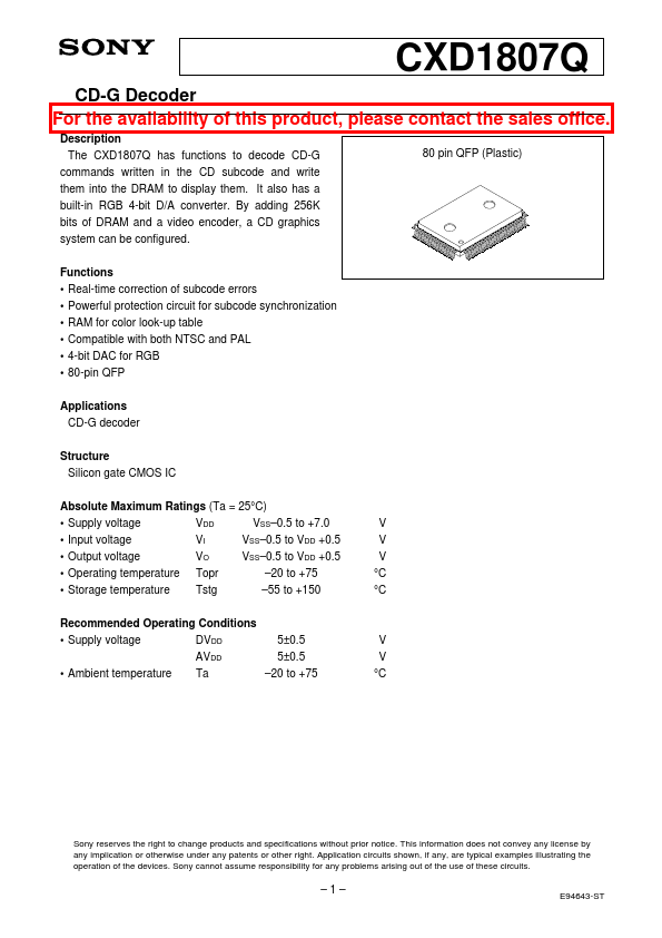
| Description | CD-G Decoder |
| Datasheet |
 CXD1807Q Datasheet CXD1807Q Datasheet
|
|
|
The CXD1807Q has functions to decode CD-G commands written in the CD subcode and write them into the DRAM to display them.
It also has a built-in RGB 4-bit D/A converter.
By adding 256K bits of DRAM and a video encoder, a CD graphics system can be configured.
Real-time correction| Part number | CXD1807Q |
|---|---|
| Manufacturer | Sony Semiconductor Solutions |
| File Size | 255.25 KB |
| Description | CD-G Decoder |
| Datasheet |
CXD1807Q Datasheet
|
|
|
|
| Part Number | Description | Manufacturer |
|---|---|---|
| CXD101-106Q | CMOS Digital Delay Line | ETC |
| CXD104-114Q | C-MOS MEMORY SEQUENCER | ETC |
| CXD1088AQ | Over Sampling Digital Filter | Sony |
| CXD1095AR | CMOS I/O Expander | ETC |
| CXD1095Q | CMOS I/O Port Expander | ETC |
| Part Number | Description |
|---|---|
| CXD1803AQ | CD-ROM DECODER |
| CXD1803AR | CD-ROM DECODER |
| CXD1804AR | CD-ROM Decoder |
| CXD1804BR | CD-ROM Decoder |
| CXD1804CR | CD-ROM Decoder |
The following content is an automatically extracted verbatim text from the original manufacturer datasheet and is provided for reference purposes only.