Download the SBL6040PT datasheet PDF.
This datasheet also covers the SBL6030PT variant, as both devices belong to the same low vf schottky barrier rectifiers family and are provided as variant models within a single manufacturer datasheet.
Key Features
Metal of silicon rectifier, majority carrier conducton.
Guard ring for transient protection.
Low power loss, high efficiency.
High current capability, low VF.
High surge capacity.
For use in low voltage, high frequency inverters, free
whelling, and polarity protection.
Full PDF Text Transcription for SBL6040PT (Reference)
Note: Below is a high-fidelity text extraction (approx. 800 characters) for
SBL6040PT. For precise diagrams, and layout, please refer to the original PDF.
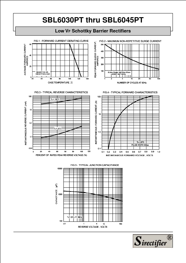
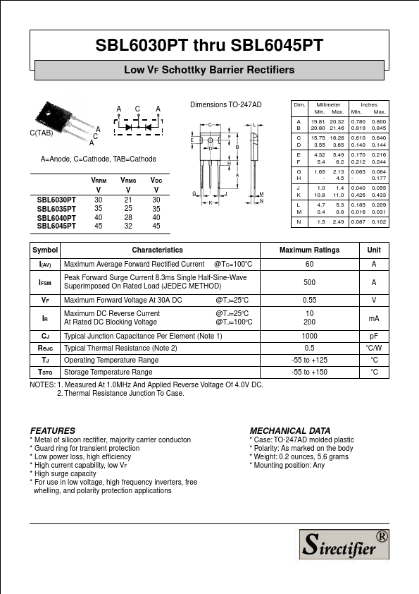
SBL6030PT thru SBL6045PT Low VF Schottky Barrier Rectifiers AC A C(TAB) A C A A=Anode, C=Cathode, TAB=Cathode SBL6030PT SBL6035PT SBL6040PT SBL6045PT VRRM V 30 35 40 45 V...
View more extracted text
B=Cathode SBL6030PT SBL6035PT SBL6040PT SBL6045PT VRRM V 30 35 40 45 VRMS V 21 25 28 32 VDC V 30 35 40 45 Dimensions TO-247AD Dim. Millimeter Min. Max. A 19.81 20.32 B 20.80 21.46 C 15.75 16.26 D 3.55 3.65 E 4.32 5.49 F 5.4 6.2 G 1.65 2.13 H - 4.5 J 1.0 1.4 K 10.8 11.0 L 4.7 5.3 M 0.4 0.8 N 1.5 2.49 Inches Min. Max. 0.780 0.800 0.819 0.845 0.610 0.640 0.140 0.144 0.170 0.216 0.212 0.244 0.065 0.084 - 0.177 0.040 0.055 0.426 0.433 0.185 0.209 0.016 0.031 0.087 0.102 Symbol Characteristics I(AV) Maximum Average Forward Rectified Current @TC=100oC IFSM Peak Forward Surge Current 8.
 SBL6040PT Datasheet