Datasheet Details
| Part number | S35390A |
|---|---|
| Manufacturer | Seiko Instruments |
| File Size | 519.86 KB |
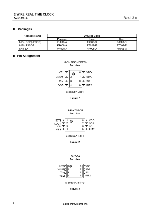
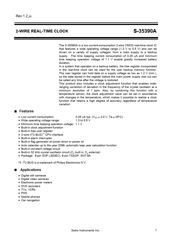
| Description | 2-Wire Real Time Clock |
| Datasheet |
 S35390A Datasheet S35390A Datasheet
|
|
|
Download the S35390A datasheet PDF. This datasheet also covers the S35-390 variant, as both devices belong to the same 2-wire real time clock family and are provided as variant models within a single manufacturer datasheet.
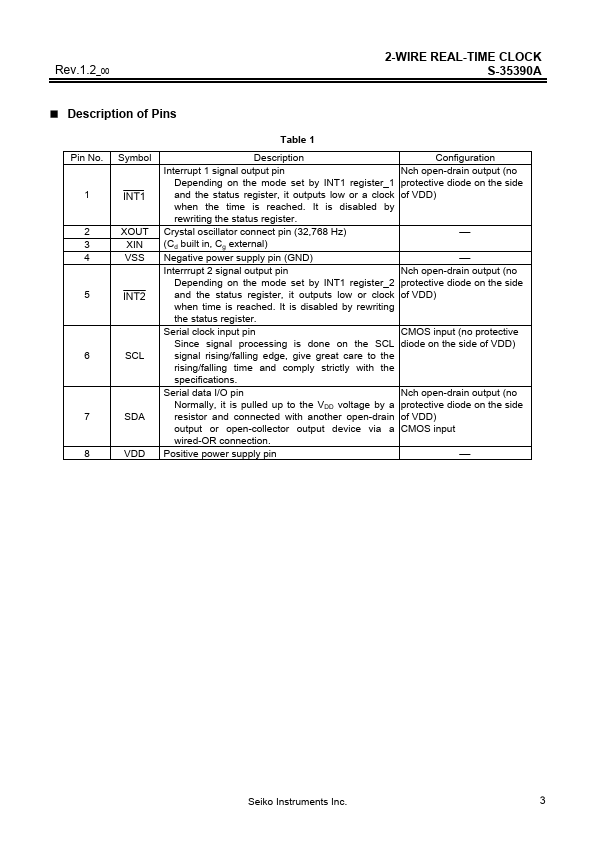
Table 1 Pin No.
Symbol Description Interrupt 1 signal output pin Depending on the mode set by INT1 register_1 and the status register, it outputs low or a clock when the time is reached.
It is disabled by rewriting the status register.
| Part number | S35390A |
|---|---|
| Manufacturer | Seiko Instruments |
| File Size | 519.86 KB |
| Description | 2-Wire Real Time Clock |
| Datasheet |
S35390A Datasheet
|
|
|
|
| Part Number | Description | Manufacturer |
|---|---|---|
| S35 | Silicon Power Rectifier | Microsemi Corporation |
| S3506I | CMOS Single Chip u-Law / A-Law Synchronous Combo Codecs | AMI |
| S3507AI | CMOS Single Chip u-Law / A-Law Synchronous Combo Codecs | AMI |
| S3507I | CMOS Single Chip u-Law / A-Law Synchronous Combo Codecs | AMI |
| S350P | Silicon NPN Phototransistor | Vishay Telefunken |
| Part Number | Description |
|---|
The following content is an automatically extracted verbatim text from the original manufacturer datasheet and is provided for reference purposes only.