Datasheet Details
| Part number | SD6861 |
|---|---|
| Manufacturer | SILAN MICROELECTRONICS |
| File Size | 244.59 KB |
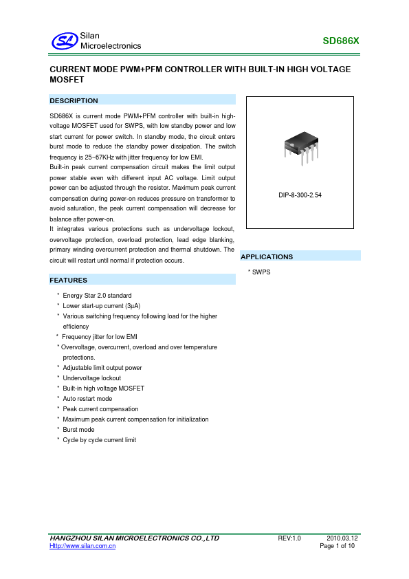
| Description | CURRENT MODE PWM+PFM CONTROLLER |
| Datasheet |
 SD6861 Datasheet SD6861 Datasheet
|
|
|
Download the SD6861 datasheet PDF (SD6860 included). The manufacturer datasheet provides complete specifications, pinout details, electrical characteristics, and typical applications for current mode pwm+pfm controller.
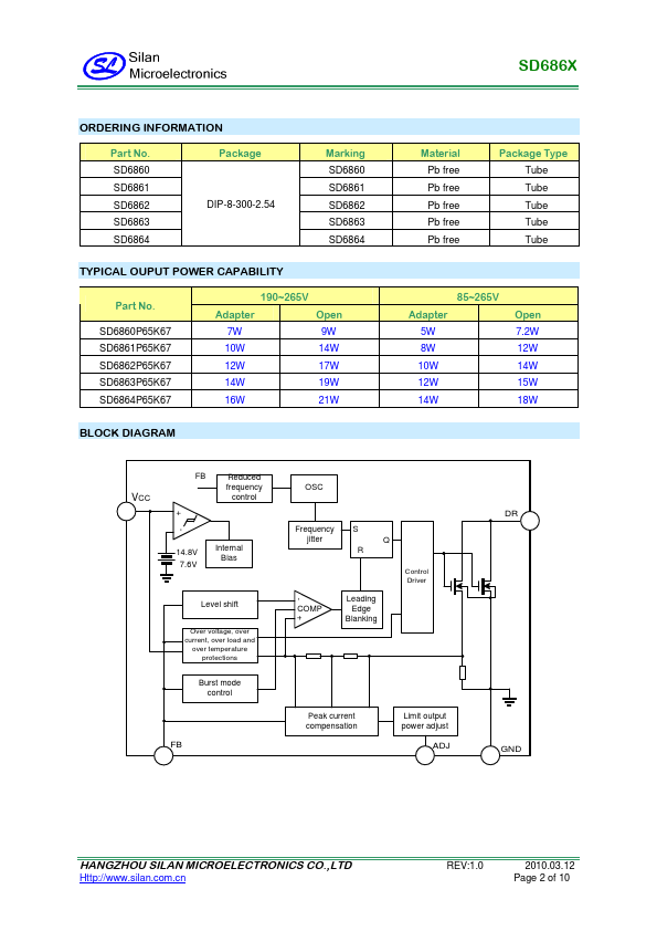
SD686X is current mode PWM+PFM controller with built-in highvoltage MOSFET used for SWPS, with low standby power and low start current for power switch.
In standby mode, the circuit enters burst mode to reduce the standby power dissipation.
| Part number | SD6861 |
|---|---|
| Manufacturer | SILAN MICROELECTRONICS |
| File Size | 244.59 KB |
| Description | CURRENT MODE PWM+PFM CONTROLLER |
| Datasheet |
SD6861 Datasheet
|
|
|
|