Datasheet Details
| Part number | HD74HC574 |
|---|---|
| Manufacturer | Renesas |
| File Size | 113.94 KB |
| Description | Octal D-type Flip-Flops |
| Datasheet |
 HD74HC574 Datasheet HD74HC574 Datasheet
|

|
|
Download the HD74HC574 datasheet PDF. This datasheet also covers the HD74HC564 variant, as both devices belong to the same octal d-type flip-flops family and are provided as variant models within a single manufacturer datasheet.
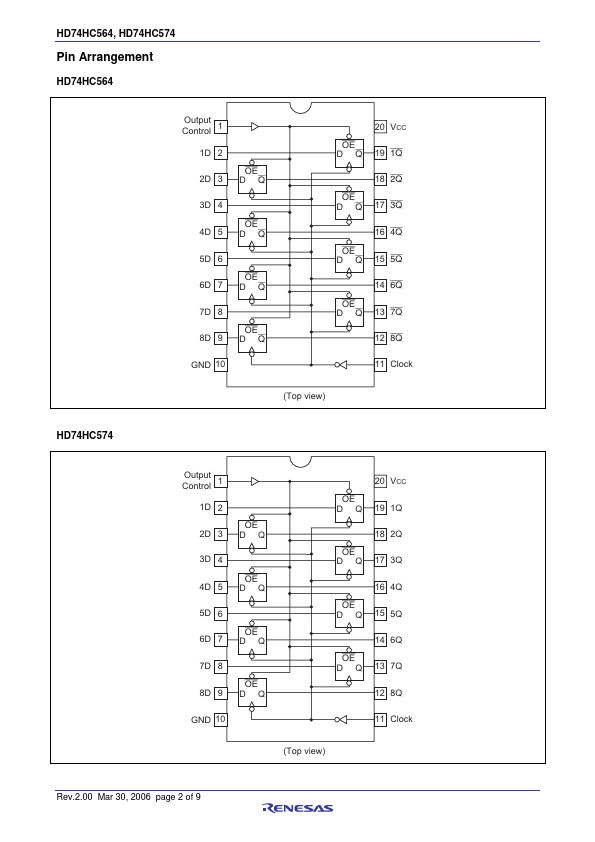
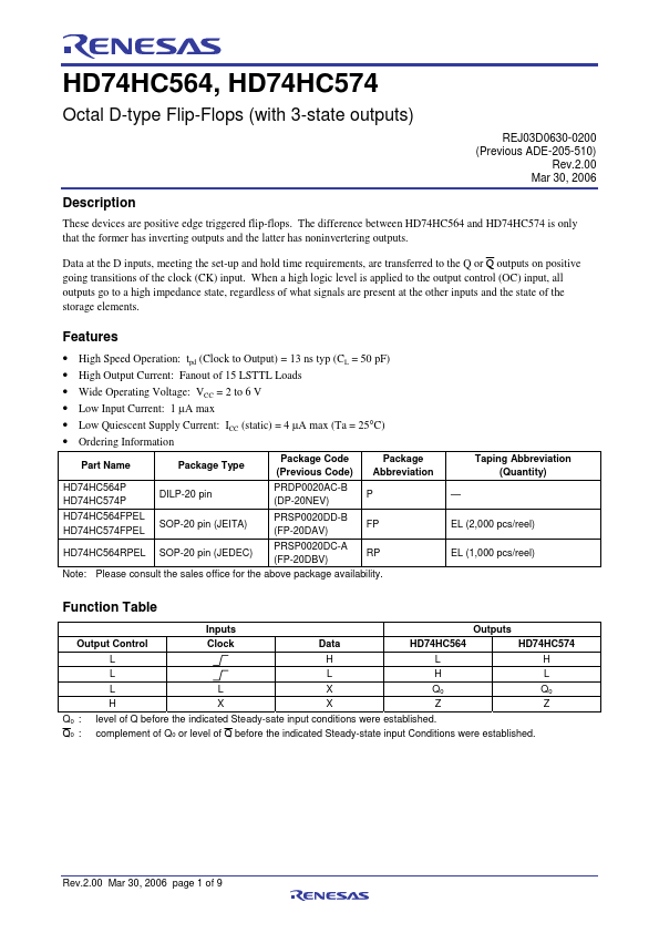
These devices are positive edge triggered flip-flops.
The difference between HD74HC564 and HD74HC574 is only that the former has inverting outputs and the latter has noninvertering outputs.
| Part number | HD74HC574 |
|---|---|
| Manufacturer | Renesas |
| File Size | 113.94 KB |
| Description | Octal D-type Flip-Flops |
| Datasheet |
HD74HC574 Datasheet
|
|
|
|
| Part Number | Description | Manufacturer |
|---|---|---|
| HD74HC574 | Octal D-type Flip-Flop | Hitachi Semiconductor |
| HD74HC573 | Octal Transparent Latches | Hitachi Semiconductor |
| HD74HC51 | AND-OR-INVERT Gate | Hitachi Semiconductor |
| HD74HC533 | Octal D-type Transparent Latches | Hitachi Semiconductor |
| HD74HC534 | Octal D-type Flip-Flop | Hitachi Semiconductor |
| Part Number | Description |
|---|---|
| HD74HC574P | Octal D-type Flip-Flops |
| HD74HC573 | Octal Transparent Latches |
| HD74HC51 | AND-OR-INVERT Gate |
| HD74HC533 | Octal D-type Transparent Latches |
| HD74HC534 | Octal D-type Flip-Flops |
The following content is an automatically extracted verbatim text from the original manufacturer datasheet and is provided for reference purposes only.