Datasheet Details
| Part number | PT5616 |
|---|---|
| Manufacturer | PTC |
| File Size | 344.52 KB |
| Description | 3-Phase 600V Gate Driver |
| Datasheet |
 PT5616 Datasheet PT5616 Datasheet
|
|
|
This page provides the datasheet information for the PT5616, a member of the PT5616A 3-Phase 600V Gate Driver family.
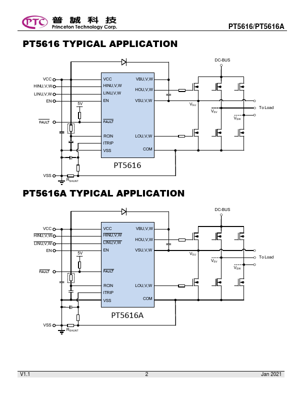
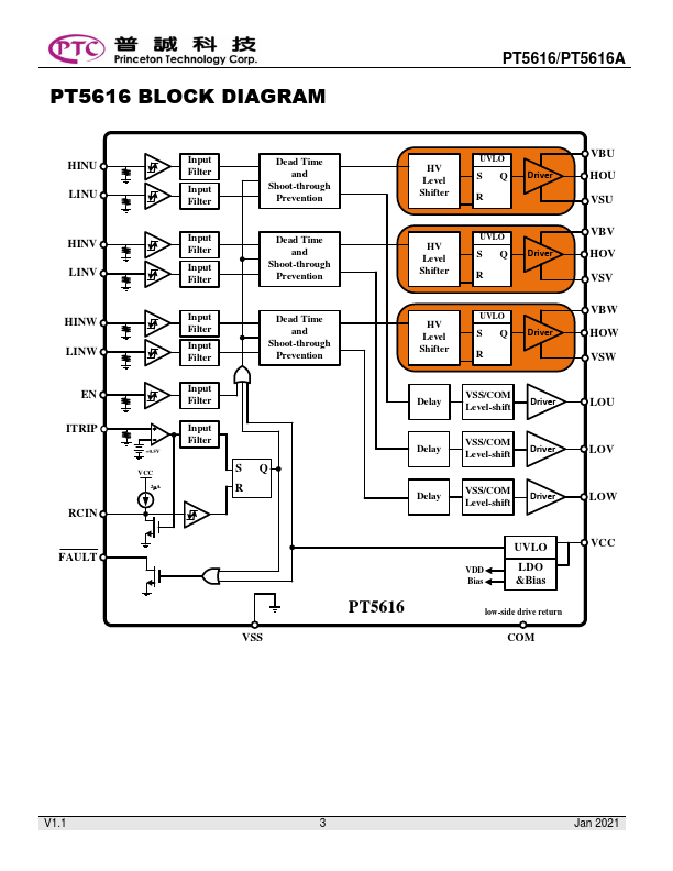
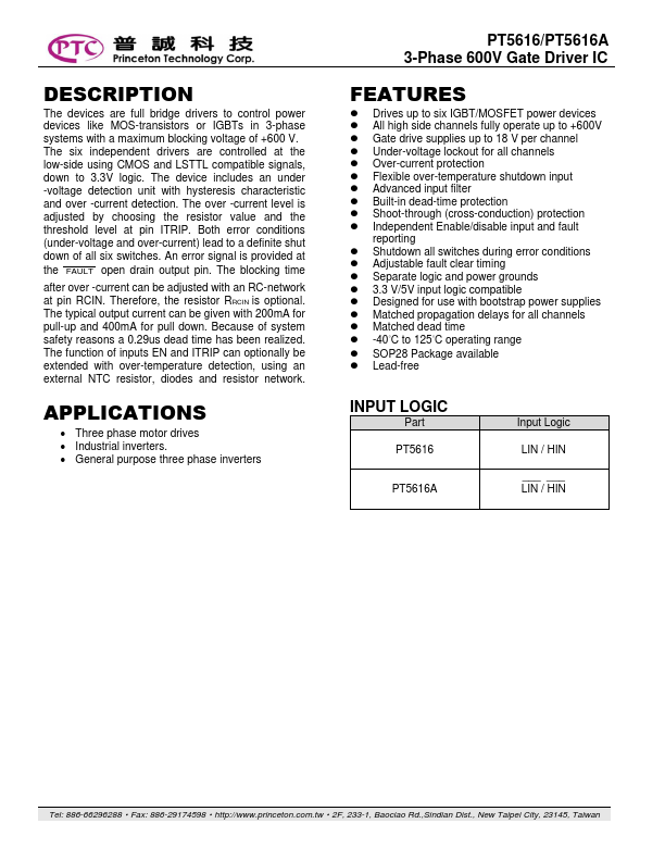
The devices are full bridge drivers to control power devices like MOS-transistors or IGBTs in 3-phase systems with a maximum blocking voltage of +600 V.
The six independent drivers are controlled at the low-side using CMOS and LSTTL compatible signals, down to 3.3V logic.
| Part number | PT5616 |
|---|---|
| Manufacturer | PTC |
| File Size | 344.52 KB |
| Description | 3-Phase 600V Gate Driver |
| Datasheet |
PT5616 Datasheet
|
|
|
|