Datasheet4U Logo Datasheet4U.com

NIMD6001ANR2G - Dual N-Channel Driver

Download the NIMD6001ANR2G datasheet PDF. This datasheet also covers the NIMD6001N variant, as both devices belong to the same dual n-channel driver family and are provided as variant models within a single manufacturer datasheet.

Description

Pin # Symbol 1 S1 2 G1 3 S2 4 G2 5 Diag/Fbk 6 D2 7 Disable 8 D1 Description FET 1 Source and Body FET 1 Gate FET 2 Source and Body FET 2 Gate Diagnostic Feedback

This pin will be logic high when either FET Drain-Source voltage exceeds the Drain Diagnostic threshold.

Features

  • RDSON 110 mW Maximum at VGS = 10 V.
  • Avalanche Energy Specified.
  • Gate Drive Disable Input.
  • Drain-Source Voltage Diagnostic Feedback Output.
  • Electrically Isolated Drains for Low Crosstalk.
  • Internal Resistors Limit Peak Transient gate Current.
  • AEC.
  • Q101 Qualified and PPAP Capable.
  • These Devices are Pb.
  • Free and are RoHS Compliant.

📥 Download Datasheet

Note: The manufacturer provides a single datasheet file (NIMD6001N-ONSemiconductor.pdf) that lists specifications for multiple related part numbers.

Full PDF Text Transcription

Click to expand full text
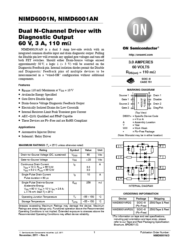
NIMD6001N, NIMD6001AN Dual N-Channel Driver with Diagnostic Output 60 V, 3 A, 110 mW NIMD6001N/AN is a dual 3 Amp low-side switch with an integrated common disable input and drain diagnostic output. Pulling the Disable pin low will override any applied gate voltages and turn off both FET switches. Should either Drain-Source voltage exceed approximately 50 V, a logic 1 (> 3 V) will be asserted on the Diagnostic/Feedback pin. Internal isolation diodes permit the Disable and Diagnostic/ Feedback pins of multiple devices to be interconnected in a “wired-OR” configuration without additional components.
Published: |