Datasheet Details
| Part number | NCP81148 |
|---|---|
| Manufacturer | ON Semiconductor |
| File Size | 182.83 KB |
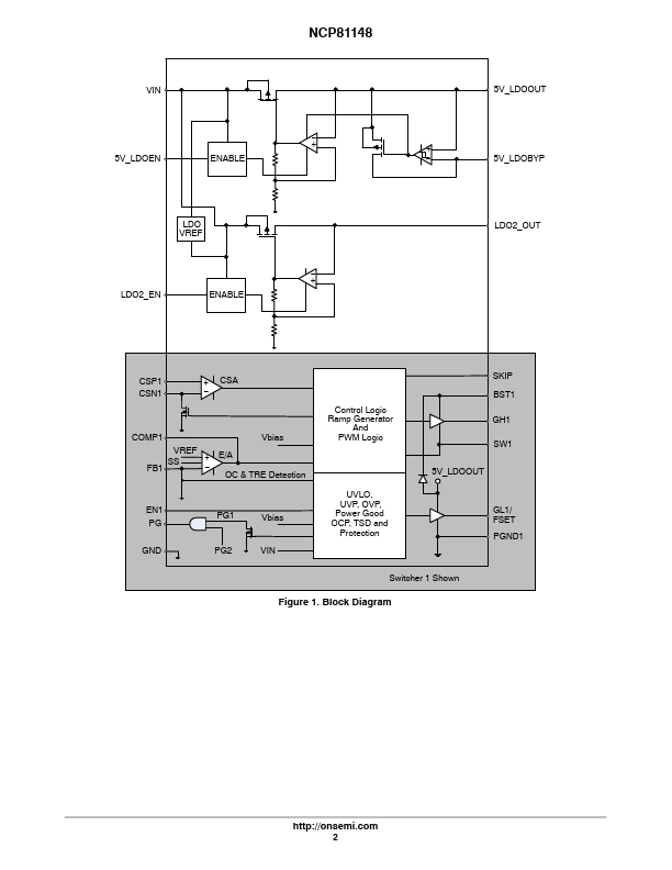
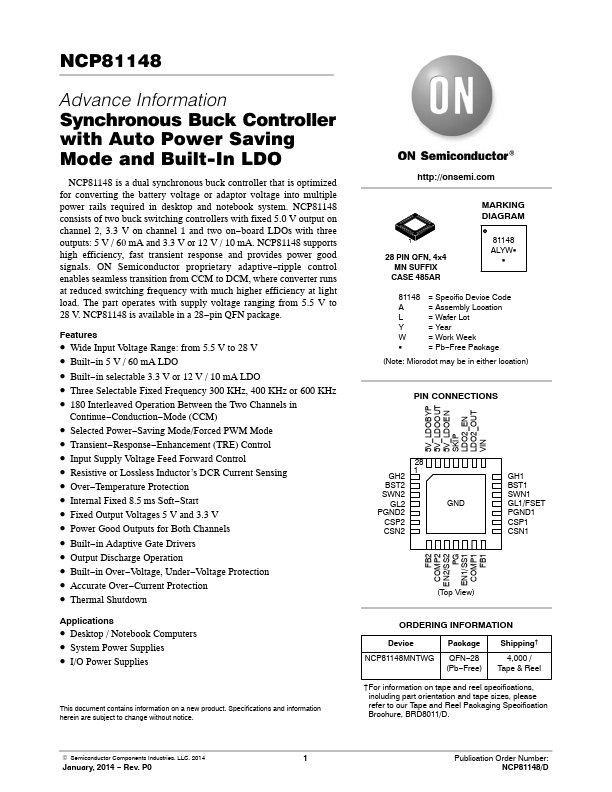
| Description | Synchronous Buck Controller |
| Datasheet |
 NCP81148 Datasheet NCP81148 Datasheet
|
|
|
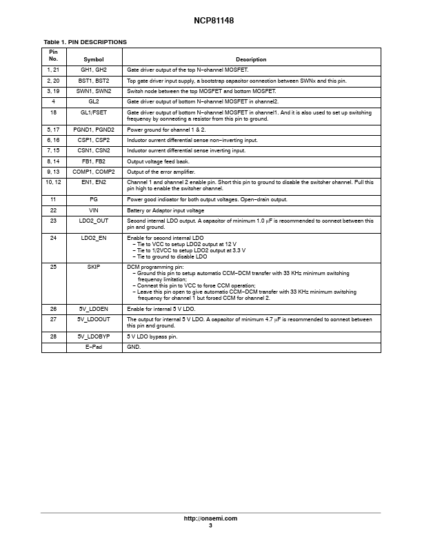
Pin No.
channel MOSFET.
Top gate driver input supply, a bootstrap capacitor connection between SWNx and this pin.
Switch node between the top MOSFET and bottom MOSFET.
| Part number | NCP81148 |
|---|---|
| Manufacturer | ON Semiconductor |
| File Size | 182.83 KB |
| Description | Synchronous Buck Controller |
| Datasheet |
NCP81148 Datasheet
|
|
|
|