Datasheet4U Logo Datasheet4U.com

NCP1402 - PFM Step-Up Micropower Switching Regulator

Datasheet Summary

Description

Pin # Symbol Pin Description 1 CE Chip Enable pin (1) The chip is enabled if a voltage which is equal to or greater than 0.9 V is applied (2) The chip is disabled if a voltage which is less than 0.3 V is applied (3) The chip will be enabled if it is left floating 2 OUT Output voltage mo

Features

  • Extremely Low Startup Voltage of 0.8 V.
  • Operation Down to Less than 0.3 V.
  • High Efficiency 85% (Vin = 2.0 V, VOUT = 3.0 V, 70 mA).
  • Low Operating Current of 30 mA (VOUT = 1.9 V).
  • Output Voltage Accuracy ±2.5%.
  • Low Converter Ripple with Typical 30 mV.
  • Only Three External Components Are Required.
  • Chip Enable Power Down Capability for Extended Battery Life.
  • Micro Miniature Thin SOT.
  • 23.
  • 5 Packages.

📥 Download Datasheet

Datasheet preview – NCP1402

Datasheet Details

Part number NCP1402
Manufacturer ON Semiconductor
File Size 435.08 KB
Description PFM Step-Up Micropower Switching Regulator
Datasheet download datasheet NCP1402 Datasheet
Additional preview pages of the NCP1402 datasheet.
Other Datasheets by ON Semiconductor

Full PDF Text Transcription

Click to expand full text
NCP1402 
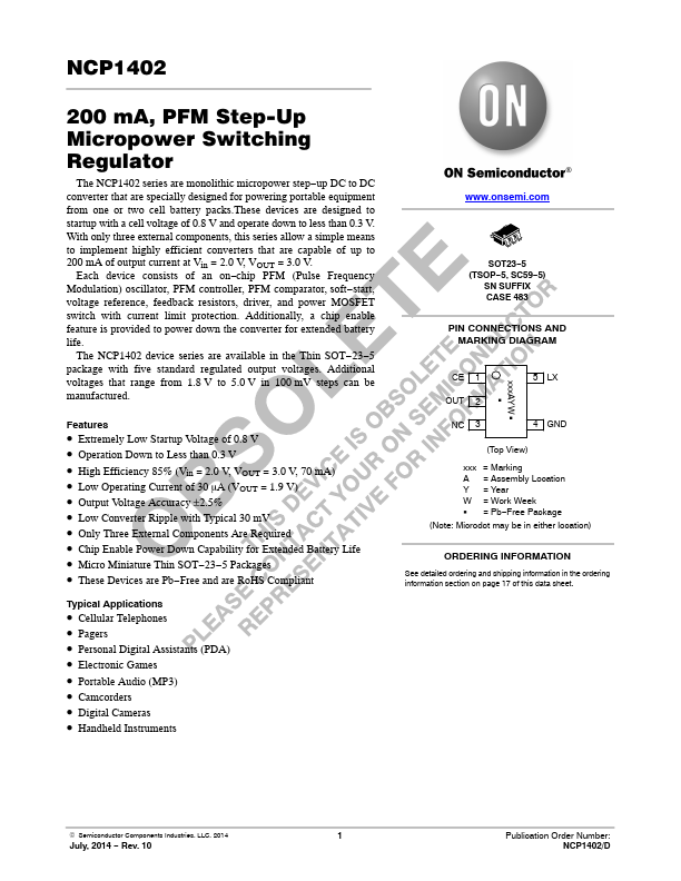
200 mA, PFM Step-Up Micropower Switching Regulator 
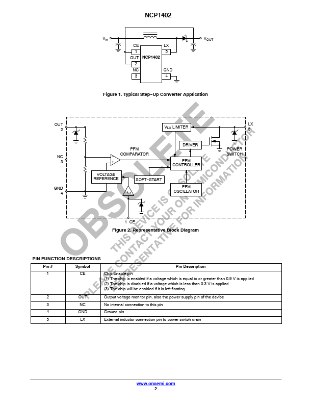
The NCP1402 series are monolithic micropower step−up DC to DC converter that are specially designed for powering portable equipment from one or two cell battery packs.These devices are designed to startup with a cell voltage of 0.8 V and operate down to less than 0.3 V. With only three external components, this series allow a simple means to implement highly efficient converters that are capable of up to 200 mA of output current at Vin = 2.0 V, VOUT = 3.0 V. Each device consists of an on−chip PFM (Pulse Frequency Modulation) oscillator, PFM controller, PFM comparator, soft−start, voltage reference, feedback resistors, driver, and power MOSFET switch with current limit protection.
Published: |