Datasheet4U Logo Datasheet4U.com

NCP1337 - PWM Current Mode Controller

Datasheet Summary

Description

Pin No.

out and external triggering 2 FB Sets the peak current setpoint 3 CS Current sense input and overpower compensation adjustment 4 GND IC ground 5 DRV Output driver 6 VCC IC supply 8 HV High voltage pin Description

Features

  • an efficient protective circuitry which, in presence of an overcurrent condition, disables the output pulses and enters a safe burst mode, trying to restart. Once the default has gone, the device auto.
  • recovers. Also included is a bulk voltage monitoring function (known as brown.
  • out protection), an adjustable overpower compensation, and a VCC OVP. The controller immediately restarts after any of these conditions, unless the fault timer has timed out. Finally, an internal 4.0 ms so.

📥 Download Datasheet

Datasheet preview – NCP1337

Datasheet Details

Part number NCP1337
Manufacturer ON Semiconductor
File Size 257.76 KB
Description PWM Current Mode Controller
Datasheet download datasheet NCP1337 Datasheet
Additional preview pages of the NCP1337 datasheet.
Other Datasheets by ON Semiconductor

Full PDF Text Transcription

Click to expand full text
DATA SHEET www.onsemi.com
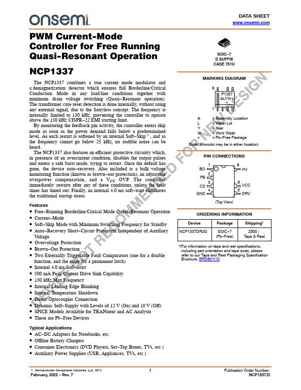
 PWM Current-Mode Controller for Free Running Quasi-Resonant Operation NCP1337 
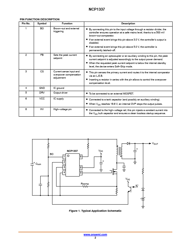
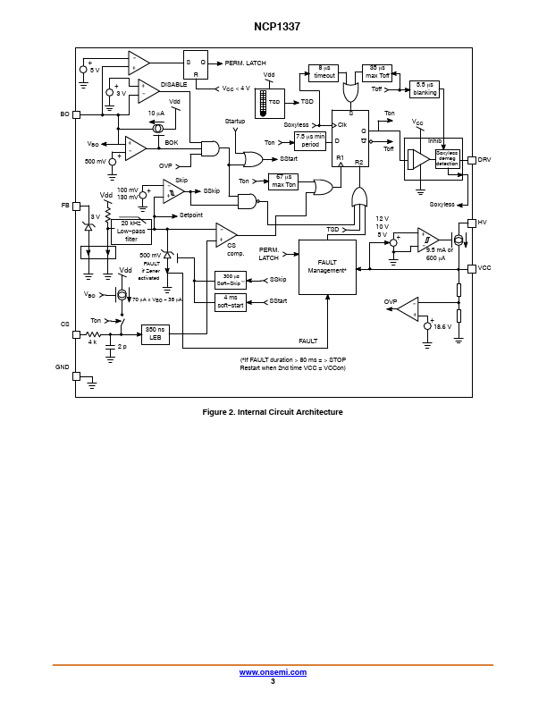
The NCP1337 combines a true current mode modulator and a demagnetization detector which ensures full Borderline/Critical Conduction Mode in any load/line conditions together with minimum drain voltage switching (Quasi−Resonant operation). The transformer core reset detection is done internally, without using any external signal, due to the Soxyless concept. The frequency is internally limited to 130 kHz, preventing the controller to operate above the 150 kHz CISPR−22 EMI starting limit. By monitoring the feedback pin activity, the controller enters skip mode as soon as the power demand falls below a predetermined level.
Published: |