Datasheet Details
| Part number | MC74LVXT4053 |
|---|---|
| Manufacturer | onsemi |
| File Size | 467.92 KB |
| Description | Analog Multiplexer/Demultiplexer |
| Datasheet |
 MC74LVXT4053 Datasheet MC74LVXT4053 Datasheet
|
|
|
Download the MC74LVXT4053 datasheet PDF. This datasheet also covers the MC74LVX4051 variant, as both devices belong to the same analog multiplexer/demultiplexer family and are provided as variant models within a single manufacturer datasheet.
| Part number | MC74LVXT4053 |
|---|---|
| Manufacturer | onsemi |
| File Size | 467.92 KB |
| Description | Analog Multiplexer/Demultiplexer |
| Datasheet |
MC74LVXT4053 Datasheet
|
|
|
|
Note: Below is a high-fidelity text extraction (approx. 800 characters) for MC74LVXT4053. For precise diagrams, and layout, please refer to the original PDF.
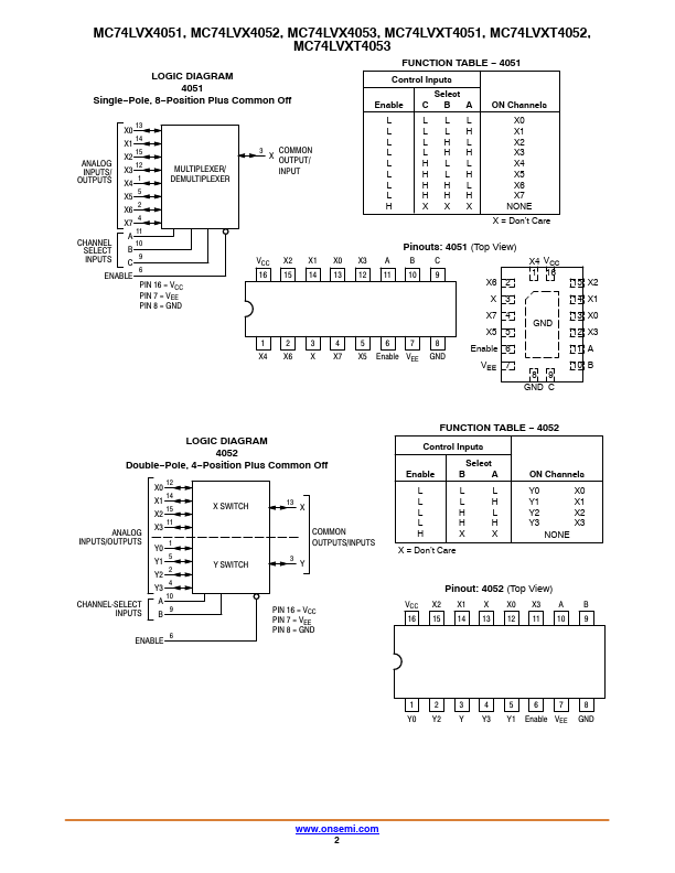
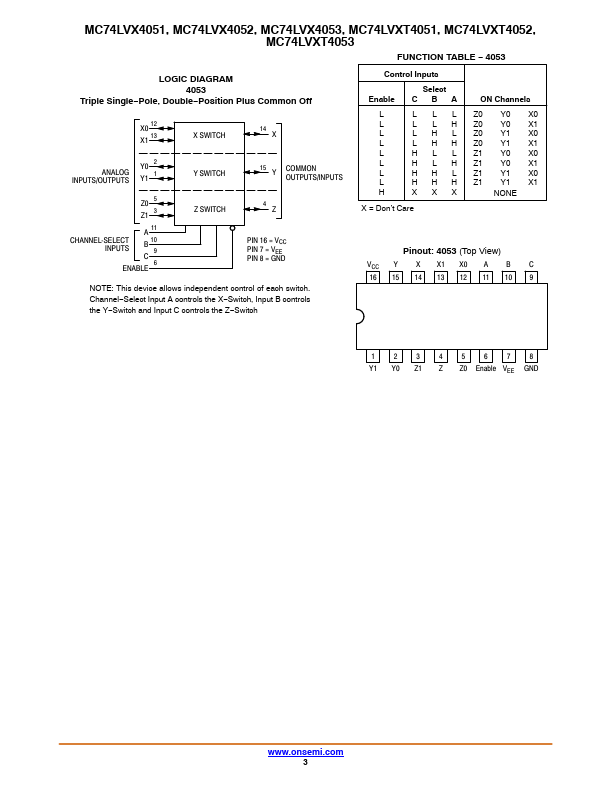
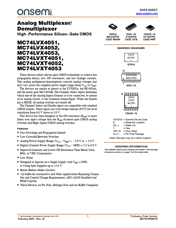
DATA SHEET www.onsemi.com Analog Multiplexer/ Demultiplexer High−Performance Silicon−Gate CMOS MC74LVX4051, MC74LVX4052, MC74LVX4053, MC74LVXT4051, MC74LVXT4052, MC74LVXT...
| Part Number | Description |
|---|---|
| MC74LVXT4051 | Analog Multiplexer/Demultiplexer |
| MC74LVXT4052 | Analog Multiplexer/Demultiplexer |
| MC74LVXT4066 | Quad Analog Switch/Multiplexer/Demultiplexer |
| MC74LVXT8051 | Analog Multiplexer/Demultiplexer |
| MC74LVXT8053 | Analog Multiplexer/Demultiplexer |
| MC74LVX00 | Quad 2-Input NAND Gate |
| MC74LVX02 | Quad 2-Input NOR Gate |
| MC74LVX04 | Hex Inverter |
| MC74LVX08 | Quad 2-Input NAND Gate |
| MC74LVX125 | Quad Bus Buffer |