Datasheet Details
| Part number | LM494 |
|---|---|
| Manufacturer | National Semiconductor (now Texas Instruments) |
| File Size | 159.34 KB |
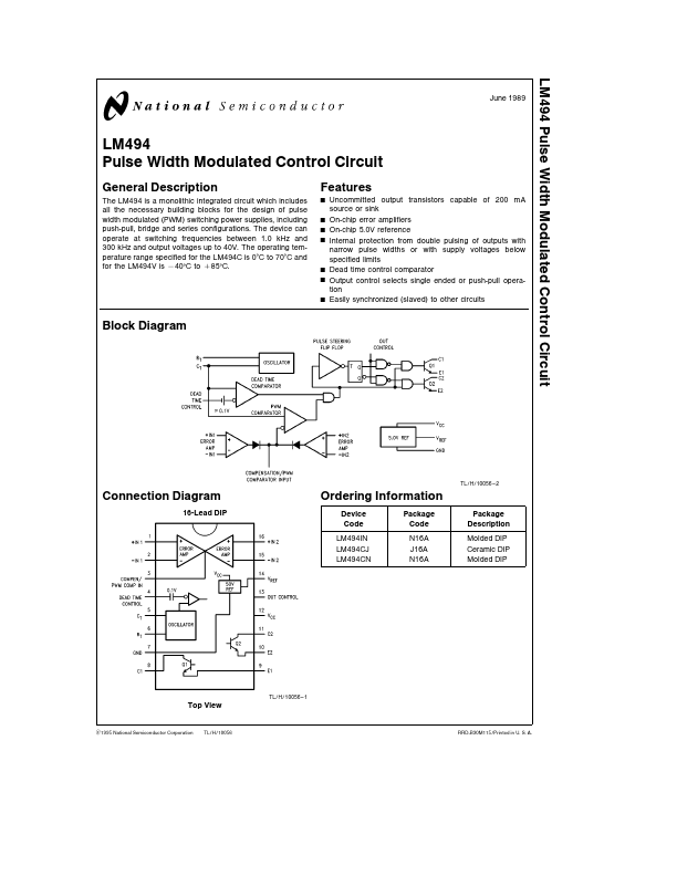
| Description | Pulse Width Modulated Controller |
| Datasheet |
 LM494 Datasheet LM494 Datasheet
|
|
|
| Part number | LM494 |
|---|---|
| Manufacturer | National Semiconductor (now Texas Instruments) |
| File Size | 159.34 KB |
| Description | Pulse Width Modulated Controller |
| Datasheet |
LM494 Datasheet
|
|
|
|
| Part Number | Description | Manufacturer |
|---|---|---|
| LM4940 | 6W Stereo Audio Power Amplifier | Texas Instruments |
| LM4941 | 1.25 Watt Fully Differential Audio Power Amplifier | Texas Instruments |
| LM4941SDBD | 1.25 Watt Fully Differential Audio Power Amplifier | Texas Instruments |
| LM4941TMBD | 1.25 Watt Fully Differential Audio Power Amplifier | Texas Instruments |
| LM49450 | Class D Audio SubSystem | Texas Instruments |
| Part Number | Description |
|---|---|
| LM4940 | 6W Stereo Audio Power Amplifier |
| LM4940 | 6W Stereo Audio Power Amplifier |
| LM4941 | 1.25 Watt Fully Differential Audio Power Amplifier |
| LM4946 | Output Capacitor Less Audio Subsystem |
| LM4947 | Mono Class D and Stereo Audio Subsystem |
The following content is an automatically extracted verbatim text from the original manufacturer datasheet and is provided for reference purposes only.